This post is older than 2 years and might not be relevant anymore
More Info: Consider searching for newer posts

clock source on ble_app_uart

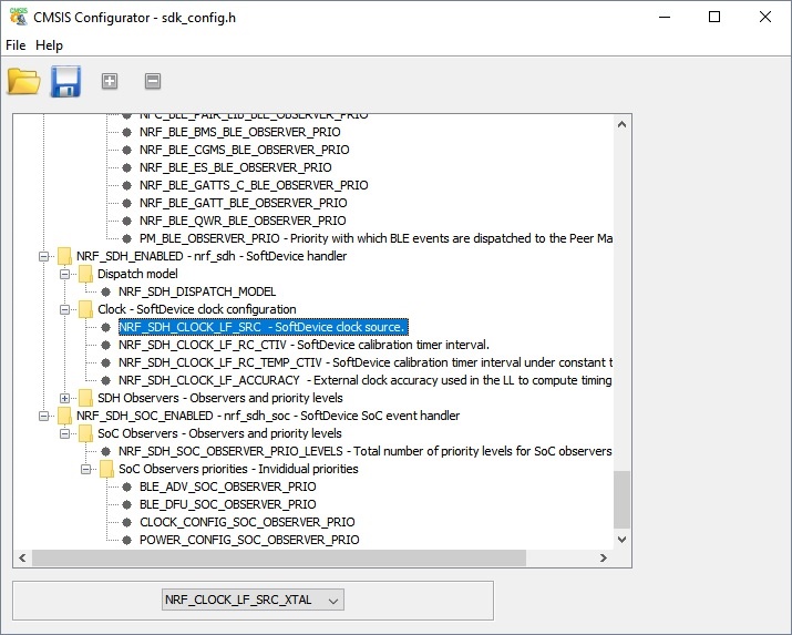
From what I understand the clock source for the example ble_app_uart is the 32 KHz external crystal. Please, see the screenshot of the CMSIS configurator:

How do I set the external 32 MHz crystal?

I am using the development board PCA10040, SDK 15 and softdevice 6.0.

Best regards

Parents
  • Hi,

    As you may know there are two clock controllers in the nRF52, one high frequency (HF) and one low frequency (LF). As shown here, there are two sources for the HF clock:

    1. External crystal (HFXO)
    2. Internal oscillator (HFINT)

    and three for the LF clock:

    1. External crystal (LFXO)
    2. Internal oscillator (LFRC)
    3. Synthesized from the HF clock controller (LFSYNT). 

    The settings you are referring to are used by the Softdevice to select LF clock source. I'm not sure if I understand your question, but LFSYNT is not intended to be used with the Softdevice. LFXO is better for current consumption, but obviously requires that your design has a crystal. If you don't have a crystal you can use LFRC instead. 

    There is no need to specify HF clock source for the Softdevice. A HF crystal is mandatory, and the Softdevice will dynamically switch between HFXO and HFINT to save current. 

  • Hello, I used a timer as input capture to measure the period of a square waveform; I left the original settings of example, but when I measured the actual period of 11.579 ms, I measured 11.656 ms with an error of 77 us.

    Then I used the API sd_clock_hfclk_request() (please, see the initialization of my main)


        // Initialize.
        // init_ADP144();  // da abilitare quando è collegato il sensore
        uart_init();
        
        log_init();
        timers_init();
    
        nrf_gpio_cfg_output(OUT_COMP);  // pin per visualizzare l'uscita digitale
        //nrf_gpio_cfg(OUT_COMP, NRF_GPIO_PIN_DIR_OUTPUT, NRF_GPIO_PIN_INPUT_DISCONNECT, NRF_GPIO_PIN_PULLDOWN/*NRF_GPIO_PIN_NOPULL*/, NRF_GPIO_PIN_H0H1, NRF_GPIO_PIN_NOSENSE);
        
        //lpcomp_init();
        //saadc_init();
        //IC1_init();
        
        flag_connected = 0;
    
        //buttons_leds_init(&erase_bonds);
        power_management_init();
        ble_stack_init();
        gap_params_init();
        gatt_init();
        services_init();
        advertising_init();
        conn_params_init();
    
        //********************************************
        sd_clock_hfclk_request(); 	
        //********************************************
    
        // Start execution.
        printf("\r\nUART started.\r\n");
        NRF_LOG_INFO("Debug logging for UART over RTT started.");
        value = 105;
        sprintf(debug_str, "valore di variabile = %d", value);
        NRF_LOG_INFO("%s",(uint32_t)debug_str);
    
        advertising_start();
    
        lpcomp_init();
        saadc_init();
        IC1_init();

    and I measured 11.579 ms with no error. But I'm not sure if I used correctly the API sd_clock_hfclk_request().

    Finally what is the settings to have the maximum precision to make a measure with a timer?

    Best regards

  • If you need accurate timings then what you are doing is correct.

    The HFINT has a poor accuracy, but the crystal typically has an accuracy of only 20 ppm. sd_clock_hfclk_request() is used to make HFXO run continuously which gives you optimal accuracy at all times. 

  • Ok, thank you for the support

    I added the check if the crystal is started

        //********************************************
        sd_clock_hfclk_request();
        p_is_running = 0;
        while (!p_is_running)
        {
            sd_clock_hfclk_is_running(&p_is_running);
        }
        //********************************************

    Best regards

Reply Children
Related