hi all!
Like two of my predecessors, I am trying to put a CR95HF into operation. I chose the nRF52832 DK as MCU (SDK 15).
[thread=https://devzone.nordicsemi.com/f/nordic-q-a/34668/error-communicating-with-cr95hf-over-spi-with-dk52]click me[/thread]
[thread=https://devzone.nordicsemi.com/f/nordic-q-a/29253/using-the-spi-example-to-communicate-with-a-cr95hf/132887#132887]click me[/thread]
According to the data sheet of the CR95HF, the SPI interface works in 3 steps:
1. send command
2. poll with 0x03 until SPI return bit 3 to 1
3. send command 0x02 to read
The command is preceded by a control byte:
-
0x00: Send command to the CR95HF
-
0x03: Poll the CR95HF
-
0x02: Read data from the CR95HF
-
0x01: Reset the CR95HF
The SPI_SS line is used to select a device on the common SPI bus. The SPI_SS pin is active low.
in the following you can see my code.
SPI configuration:
[code]
void spi_event_handler(nrf_drv_spi_evt_t const * p_event,
void * p_context)
{
spi_xfer_done = true;
NRF_LOG_INFO("Transfer completed.");
if (m_rx_buf[0] != 0)
{
NRF_LOG_INFO(" Received:");
NRF_LOG_HEXDUMP_INFO(m_rx_buf, strlen((const char *)m_rx_buf));
}
}
nrf_drv_spi_config_t spi_config = NRF_DRV_SPI_DEFAULT_CONFIG;
spi_config.ss_pin = NRF_DRV_SPI_PIN_NOT_USED;; // pin 29
spi_config.miso_pin = SPI_MISO_PIN; // pin 28
spi_config.mosi_pin = SPI_MOSI_PIN; // pin 4
spi_config.sck_pin = SPI_SCK_PIN; // pin 3
spi_config.orc = 0xFF;
spi_config.mode = NRF_DRV_SPI_MODE_0;
spi_config.frequency = NRF_DRV_SPI_FREQ_1M;
spi_config.bit_order = NRF_DRV_SPI_BIT_ORDER_MSB_FIRST;
APP_ERROR_CHECK(nrf_drv_spi_init(&spi, &spi_config, spi_event_handler, NULL));
[/code]
wake-up pulse for CR95HF (see datasheet);
[code]
// CR95HF Wake-Up Pulse
nrf_delay_ms(12);
nrf_gpio_pin_set(IRQ_PIN); // pulse to put the
nrf_delay_us(200);
nrf_gpio_pin_clear(IRQ_PIN); // mode
nrf_delay_us(20);
nrf_gpio_pin_set(IRQ_PIN); // pulse to put the
nrf_delay_ms(12);
[/code]
step 1, send the command:
[code]
nrf_gpio_pin_clear(SPI_SS_PIN);
spi_xfer_done = false;
APP_ERROR_CHECK(nrf_drv_spi_transfer(&spi, invcommand, 5, m_rx_buf, 5));
while (!spi_xfer_done){__WFE();}
nrf_gpio_pin_set(SPI_SS_PIN);
nrf_delay_ms(1);
[/code]
step 2, poll for data ready:
[code]
nrf_gpio_pin_clear(SPI_SS_PIN);
while(m_rx_buf[0] != 8) {
spi_xfer_done = false;
m_tx_buf[0] = 0x03;
APP_ERROR_CHECK(nrf_drv_spi_transfer(&spi, m_tx_buf, 1, m_rx_buf, 1));
while (!spi_xfer_done){__WFE();}
m_rx_buf[0] = m_rx_buf[0] & 0x08;
}
nrf_gpio_pin_set(SPI_SS_PIN);
nrf_delay_ms(1);
[/code]
step 3, read the data:
[code]
memset(echo_idn, 0, sizeof(echo_idn));
nrf_gpio_pin_clear(SPI_SS_PIN);
spi_xfer_done = false;
APP_ERROR_CHECK(nrf_drv_spi_transfer(&spi, &read, 1, echo_idn, sizeof(echo_idn)));
while (!spi_xfer_done){__WFE();}
nrf_gpio_pin_set(SPI_SS_PIN);
nrf_delay_ms(1);
[/code]
variable:
[code]
#define IRQ_PIN 27
#define SPI_INSTANCE 1 /**< SPI instance index. */
static const nrf_drv_spi_t spi = NRF_DRV_SPI_INSTANCE(SPI_INSTANCE); /**< SPI instance. */
static volatile bool spi_xfer_done; /**< Flag used to indicate that SPI instance completed the transfer. */
#define TEST_STRING "Nordic"
static uint8_t m_tx_buf[] = TEST_STRING; /**< TX buffer. */
static uint8_t m_rx_buf[15]; /**< RX buffer. */
static const uint8_t m_length = sizeof(m_tx_buf); /**< Transfer length. */
static uint8_t ready_read = 0x03;
static uint8_t respons_ready_read;
static uint8_t read_tag[5] = {0x04, 0x03, 0x26, 0x01, 0x00};
static uint8_t tag[10];
static uint8_t idn[3] = {0x00, 0x01, 0x00};
static uint8_t echo_idn[25];
static uint8_t read = 0x02;
static uint8_t rread[15];
static uint8_t rtag[5] = {0x04, 0x03, 0x02, 0x20, 0x00};
static uint8_t resp_tag[10];
uint8_t invcommand[5] = {0x00, 0x02, 0x02, 0x01,0x21};
uint8_t sendrecv[6] = {0x00, 0x04, 0x03, 0x26, 0x01, 0x00};
[/code]
not all of them variable are used.
i found these steps from the DK BM019 data sheet (page 21).
http://www.solutions-cubed.com/content/Downloads/Breakout%20Modules/DATASHEET_BM019.pdf
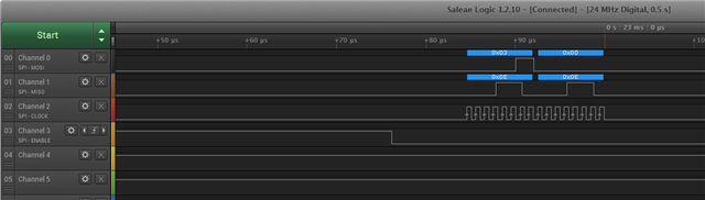
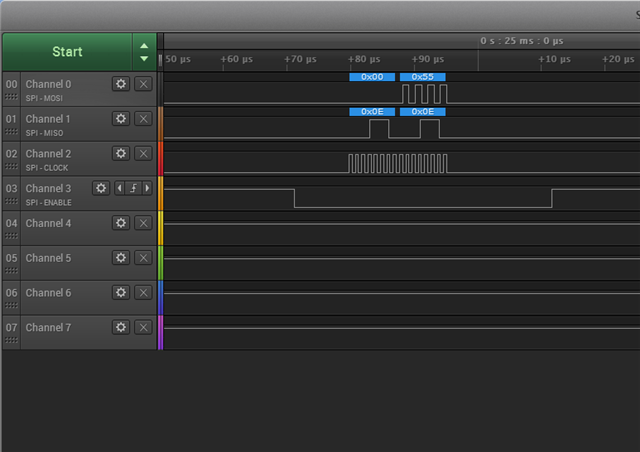
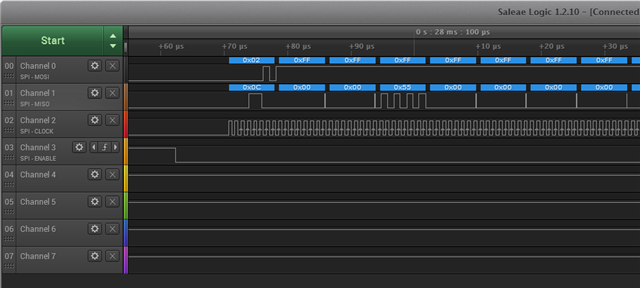
as an answer from the CR95HF I get the following:


On the first picture, you can see how I initialize the CR95HF (invcommand). on the second image, polling continues until bit nr. 3 becomes 1. on the last image, a tag should actually be read out. but I don't get anything useful there. where does that come from, what am I doing wrong? did i misunderstand the data sheet?
LuckyLukas