This post is older than 2 years and might not be relevant anymore
More Info: Consider searching for newer posts

NRF52840 sma routing

I am designing a simple broadcaster using an sma connector for a dipole antenna.

I have added a 50 ohm SMA connector to the reference deign

.  

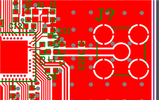
so you can see above is the placement of the SMA and the mid plane keep out. I have also added vias to join the ground planes and have omitted the bottom layer as its a complete fill.

There are vias next to the antenna feed point to join the bottom layer as much as possible.

1. Should the mid plane be bulged out for where the antenna feed pad starts to come closer?

2. is there any length considerations to the main feed line?

3. the output from the chip is from an internal balun, why are there balancing caps/conductors.

4. will this still need to be tuned for the board or is there a high likelyhood of the refrence design allready be suited for the SMA/50 ohm dipole.

Parents
  • I don't want to get too involved here since you have a big thread going on with ketilijo but...

    1. You should model your surface mount connector and not just assume that if you get the CPW on the board correct everything works out.  The feed pin on that SMA is massive and the resulting capacitive coupling to the board is severe.  Normally, SMA's have almost no ground near the feed pin as a result.  So, you need to model it in an EM simulator and/or follow the manufacturers layout guidelines.

    2. When switching to thru hole the resulting capacitance from the feed pin to the surrounding layers is even more severe.  As you have shown it above, switching that to thru hole would likely be close to a short at 2.4GHz.  Again, model the solution and don't guess or you won't be happy with the results.

    3.  Unless you have need of the right angle to board solution that thru hole provides you will get a more reliable RF solution with all the same mechanical qualities of thru hole by using an end launch sma connection instead.  Then the CPW just goes straight onto the feed pin since it is all characterized.  Normally end launch with a tab center pin is preferable to those with the round center pin for RF purposes.  But at 2.4GHz a round center pin isn't too bad.

Reply
  • I don't want to get too involved here since you have a big thread going on with ketilijo but...

    1. You should model your surface mount connector and not just assume that if you get the CPW on the board correct everything works out.  The feed pin on that SMA is massive and the resulting capacitive coupling to the board is severe.  Normally, SMA's have almost no ground near the feed pin as a result.  So, you need to model it in an EM simulator and/or follow the manufacturers layout guidelines.

    2. When switching to thru hole the resulting capacitance from the feed pin to the surrounding layers is even more severe.  As you have shown it above, switching that to thru hole would likely be close to a short at 2.4GHz.  Again, model the solution and don't guess or you won't be happy with the results.

    3.  Unless you have need of the right angle to board solution that thru hole provides you will get a more reliable RF solution with all the same mechanical qualities of thru hole by using an end launch sma connection instead.  Then the CPW just goes straight onto the feed pin since it is all characterized.  Normally end launch with a tab center pin is preferable to those with the round center pin for RF purposes.  But at 2.4GHz a round center pin isn't too bad.

Children
No Data
Related