This post is older than 2 years and might not be relevant anymore
More Info: Consider searching for newer posts

nRF24LE1 antenna 50 ohms impedance matching questions

Dear All,

i want to make a product which using nrf24le1 chip, but now i'm stuck on the antenna impedance matching issue.

i'm not very familiar  with the antenna design and have few questions below, hope could get help from you, thank you ~

Background:

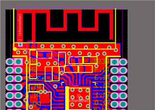
I have referred to the nRF24LE1 Product Specification and completed drawing PCB files like screen shot 3 below.  after that i decided to make a sample PCB board by PCB manufactory.

but i heard that the antenna need to do 50 ohms impedance matching and thus put me in trouble and got few questions below:

1) i use a TI sample antenna design like screen 3. does the antenna is 50 ohms if i follow all its design specification?  the antenna itself need to do 50 ohms impedance matching right ?

2)The screen shot 2 is used for Transmission line  50 ohms impedance matching right ? 

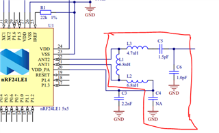
    if the material of the PCB board is different the high lighted L1 L2 L3 maybe different with the official reference correct ?

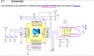
3) i found nAN24-17 described Using a 2450BM14A0002 Balun instead of  screen shot 1's matching network, how to tune the 50 ohms impedance matching if do so? or the Balun already           done impedance matching ?

4) if i use the 2450BM14A0002 Balun and connect to a 50 ohms antenna, do i still need to do the transmission line impedance matching? and how can i tell the PCB factory to do so?

i just want to make a prototype quickly but now seems it is not so easy for me, please kindly help if someone have experience, thanks a lot~

>>>screen shot 1
>>>screen shot 2

2450BM14A0002 balun
>>>screen shot 3
  • Hi,


    1. Maybe, maybe not. Based on my own experience with this I would not count on it. Note though that even if it is not perfectly 50 ohm, you will still be able to achieve wireless communication, just at a smaller range than if it was tuned. You might want to add an unpopulated pi network in case tuning is needed in the future (series component can be 0ohm resistor)
    2. The components do differential to single ended matching, and low-pass filtering of harmonics and spurious. If the reference layout is not replicated, performance will differ. You might still get decent output power, but see a drastic increase in harmonics.
    3. The balun component in screen 2 replaces the lumped matching network in screen 1, yes. It should not be as dependent on the thickness, but as you have no components to adjust the value of, it is paramount that you replicate the mounting(layout) with regards to the nRF and grounding exactly. Feel free to submit your design here for a free review.
    4. With the balun, the importance of the 50 ohm transmission line becomes larger. In your current design the transmission line between the antenna and C6 is so short that it will not cause any mismatch. With the length between the antenna and a hypothetical balun, it will be long enough that you would want to dimension the transmission line to 50 ohms to avoid risk of any performance hit. It's not the end of the world if it is 52 ohms or 45 ohms, but closer is of course better. Impedance control should not be needed, just use a free transmission line calculator, e.g. AppCAD.


    Best regards,

    Andreas

  • Hi Andreas,

    Thank you so much for your detailed explanation and guidance!

    i have send you my design files to you, please kindly help to review and give advice if any, thank you !

    Best Regards,

    Kevin.

Related