Dear All,
i want to make a product which using nrf24le1 chip, but now i'm stuck on the antenna impedance matching issue.
i'm not very familiar with the antenna design and have few questions below, hope could get help from you, thank you ~
Background:
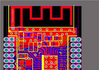
I have referred to the nRF24LE1 Product Specification and completed drawing PCB files like screen shot 3 below. after that i decided to make a sample PCB board by PCB manufactory.
but i heard that the antenna need to do 50 ohms impedance matching and thus put me in trouble and got few questions below:
1) i use a TI sample antenna design like screen 3. does the antenna is 50 ohms if i follow all its design specification? the antenna itself need to do 50 ohms impedance matching right ?
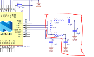
2)The screen shot 2 is used for Transmission line 50 ohms impedance matching right ?
if the material of the PCB board is different the high lighted L1 L2 L3 maybe different with the official reference correct ?
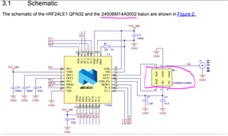
3) i found nAN24-17 described Using a 2450BM14A0002 Balun instead of screen shot 1's matching network, how to tune the 50 ohms impedance matching if do so? or the Balun already done impedance matching ?
4) if i use the 2450BM14A0002 Balun and connect to a 50 ohms antenna, do i still need to do the transmission line impedance matching? and how can i tell the PCB factory to do so?
i just want to make a prototype quickly but now seems it is not so easy for me, please kindly help if someone have experience, thanks a lot~
>>>screen shot 1
>>>screen shot 2
2450BM14A0002 balun
>>>screen shot 3