This post is older than 2 years and might not be relevant anymore
More Info: Consider searching for newer posts

Count Clock Pulses with PPI + Gpiote Then Change GPIO Depending on Count (NRF52810)

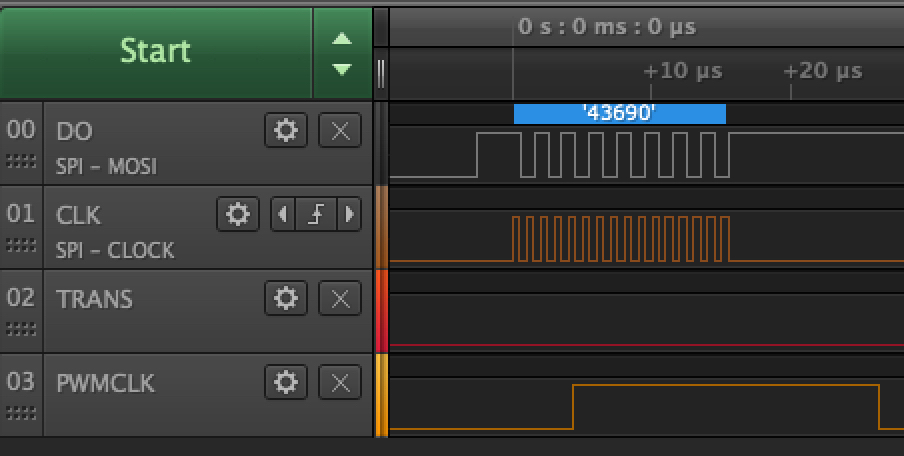
I'm attempting to use PPI and Timer2 on the NRF52810 to count the clock pulses coming out of the SPIM driver. As there is no way to do this internally (as far as I know) I tied another GPIO pin to the clock pin. The idea being here is that I want to toggle a separate "latch" pin at different places during the serialization process. With the latch pin active at different clock cycles, it signifies a different command in the LED driver I'm using. Ex. Latch pin high for 16 bits is one while only active for the last two bits is a completely different command.

I've had some success with but not 100%. Here's some code:

This is for initializing PPI, gpiote pins and timer (in counter mode)

uint32_t err;

  // change to coutner
  nrfx_timer_config_t tmr_config = NRFX_TIMER_DEFAULT_CONFIG;
  tmr_config.mode = NRF_TIMER_MODE_COUNTER;
  tmr_config.bit_width = NRF_TIMER_BIT_WIDTH_32;

  // TODO: Configure counter. No timeout handler.
  err = nrfx_timer_init(&m_counter, &tmr_config, timer_handler_count);
  VERIFY_SUCCESS(err);

  // Input & output configuration
  nrfx_gpiote_in_config_t in_config = NRFX_GPIOTE_CONFIG_IN_SENSE_LOTOHI(true);
  nrfx_gpiote_out_config_t out_config = NRFX_GPIOTE_CONFIG_OUT_TASK_HIGH;

  // Init GPIO pins
  err = nrfx_gpiote_in_init(LIS2DH_INT_PIN, &in_config, clk_in_pin_handler);
  VERIFY_SUCCESS(err);

  err = nrfx_gpiote_out_init(LED_TRANS_PIN, &out_config);
  VERIFY_SUCCESS(err);

  // Enable tasks
  nrfx_gpiote_in_event_enable(LIS2DH_INT_PIN, false);
  nrfx_gpiote_out_task_enable(LED_TRANS_PIN);

  // Configure GPIO high on counter compare event
  err = nrfx_ppi_channel_alloc(&m_latch_in_channel);
  VERIFY_SUCCESS(err);

  // Configure output after counter compare
  err = nrfx_ppi_channel_alloc(&m_latch_out_channel);
  VERIFY_SUCCESS(err);

  // Assign the channel, input event, then counts the timer
  err = nrfx_ppi_channel_assign(
      m_latch_in_channel, nrfx_gpiote_in_event_addr_get(LIS2DH_INT_PIN),
      nrfx_timer_task_address_get(&m_counter, NRF_TIMER_TASK_COUNT));
  VERIFY_SUCCESS(err);

  // Also capture the register
  err = nrfx_ppi_channel_fork_assign(
      m_latch_in_channel,
      nrfx_timer_task_address_get(&m_counter, NRF_TIMER_TASK_CAPTURE0));

  // Sets the state of the trans pin after count compare
  err = nrfx_ppi_channel_assign(m_latch_out_channel,
                                nrfx_timer_compare_event_address_get(
                                    &m_counter, NRF_TIMER_EVENT_COMPARE0),
                                nrfx_gpiote_out_task_addr_get(LED_TRANS_PIN));
  VERIFY_SUCCESS(err);

  return NRF_SUCCESS;

Then the code below is used to start the enable the counter, enable PPI before writing the SPI commands:

  // Enable these channels
  nrfx_ppi_channel_enable(m_latch_in_channel);
  nrfx_ppi_channel_enable(m_latch_out_channel);

  // With reset.
  nrfx_timer_compare(&m_counter, NRF_TIMER_CC_CHANNEL0, 5, false);
  nrfx_timer_enable(&m_counter);
  nrfx_timer_clear(&m_counter);

  // The data!
  static uint8_t data[] = {0xaa, 0xaa};

  nrfx_spim_xfer_desc_t xfer_desc = NRFX_SPIM_XFER_TX(data, 2);

  // Transfer test 16 bits
  nrfx_spim_xfer(&spi, &xfer_desc, 0);


If I fork the assignment for m_latch_in_channel I get 15 ticks (when it should be 16). If I don't, I get zero or the value that's reflected in nrfx_timer_compare(&m_counter, NRF_TIMER_CC_CHANNEL0, 5, false); no matter how many clock pulses there are.

I'm stumped to say the least. Any insight is appreciated!

Parents
  • Here's the magic incantation that I found worked.

    The setup:

      uint32_t err;
    
      // change to coutner
      nrfx_timer_config_t tmr_config = NRFX_TIMER_DEFAULT_CONFIG;
      tmr_config.mode = NRF_TIMER_MODE_COUNTER;
      tmr_config.bit_width = NRF_TIMER_BIT_WIDTH_32;
    
      // TODO: Configure counter. No timeout handler.
      err = nrfx_timer_init(&m_counter, &tmr_config, timer_handler_count);
      VERIFY_SUCCESS(err);
    
      // Input & output configuration
      nrfx_gpiote_in_config_t in_config = NRFX_GPIOTE_CONFIG_IN_SENSE_LOTOHI(true);
      nrfx_gpiote_out_config_t out_config =
          NRFX_GPIOTE_CONFIG_OUT_TASK_TOGGLE(false);
    
      // Init GPIO pins
      err = nrfx_gpiote_in_init(LIS2DH_INT_PIN, &in_config, clk_in_pin_handler);
      VERIFY_SUCCESS(err);
    
      err = nrfx_gpiote_out_init(LED_TRANS_PIN, &out_config);
      VERIFY_SUCCESS(err);
    
      // Enable tasks
      nrfx_gpiote_in_event_enable(LIS2DH_INT_PIN, false);
      nrfx_gpiote_out_task_enable(LED_TRANS_PIN);
    
      // Configure GPIO high on counter compare event
      err = nrfx_ppi_channel_alloc(&m_latch_in_channel);
      VERIFY_SUCCESS(err);
    
      // Configure output after counter compare
      err = nrfx_ppi_channel_alloc(&m_latch_out_channel);
      VERIFY_SUCCESS(err);
    
      // Assign the channel, input event, then counts the timer
      err = nrfx_ppi_channel_assign(
          m_latch_in_channel, nrfx_gpiote_in_event_addr_get(LIS2DH_INT_PIN),
          nrfx_timer_task_address_get(&m_counter, NRF_TIMER_TASK_COUNT));
      VERIFY_SUCCESS(err);
    
      // Sets the state of the trans pin after count compare
      err = nrfx_ppi_channel_assign(
          m_latch_out_channel,
          nrfx_timer_event_address_get(&m_counter, NRF_TIMER_EVENT_COMPARE1),
          nrfx_gpiote_out_task_addr_get(LED_TRANS_PIN));
      VERIFY_SUCCESS(err);
    

    Using it:

      // Enable these channels
      nrfx_ppi_channel_enable(m_latch_in_channel);
      nrfx_ppi_channel_enable(m_latch_out_channel);
    
      nrfx_gpiote_out_task_enable(LED_TRANS_PIN);
    
      // With reset.
      nrfx_timer_compare(&m_counter, NRF_TIMER_CC_CHANNEL1, 5, true);
      nrfx_timer_enable(&m_counter);
      nrfx_timer_clear(&m_counter);
    
      // The data!
      static uint8_t data[] = {0xaa, 0xaa};
    
      nrfx_spim_xfer_desc_t xfer_desc = NRFX_SPIM_XFER_TX(data, 2);
    
      // Transfer test 16 bits
      nrfx_spim_xfer(&spi, &xfer_desc, 0);

    I was using the wrong compare event to toggle the output gpio. (should use nrfx_timer_event_address_get). To get the count I used this guy: 

    nrfx_timer_capture(&m_counter, NRF_TIMER_CC_CHANNEL1);

    Toggles at te 5th bit as expected. Though a little delayed.

Reply
  • Here's the magic incantation that I found worked.

    The setup:

      uint32_t err;
    
      // change to coutner
      nrfx_timer_config_t tmr_config = NRFX_TIMER_DEFAULT_CONFIG;
      tmr_config.mode = NRF_TIMER_MODE_COUNTER;
      tmr_config.bit_width = NRF_TIMER_BIT_WIDTH_32;
    
      // TODO: Configure counter. No timeout handler.
      err = nrfx_timer_init(&m_counter, &tmr_config, timer_handler_count);
      VERIFY_SUCCESS(err);
    
      // Input & output configuration
      nrfx_gpiote_in_config_t in_config = NRFX_GPIOTE_CONFIG_IN_SENSE_LOTOHI(true);
      nrfx_gpiote_out_config_t out_config =
          NRFX_GPIOTE_CONFIG_OUT_TASK_TOGGLE(false);
    
      // Init GPIO pins
      err = nrfx_gpiote_in_init(LIS2DH_INT_PIN, &in_config, clk_in_pin_handler);
      VERIFY_SUCCESS(err);
    
      err = nrfx_gpiote_out_init(LED_TRANS_PIN, &out_config);
      VERIFY_SUCCESS(err);
    
      // Enable tasks
      nrfx_gpiote_in_event_enable(LIS2DH_INT_PIN, false);
      nrfx_gpiote_out_task_enable(LED_TRANS_PIN);
    
      // Configure GPIO high on counter compare event
      err = nrfx_ppi_channel_alloc(&m_latch_in_channel);
      VERIFY_SUCCESS(err);
    
      // Configure output after counter compare
      err = nrfx_ppi_channel_alloc(&m_latch_out_channel);
      VERIFY_SUCCESS(err);
    
      // Assign the channel, input event, then counts the timer
      err = nrfx_ppi_channel_assign(
          m_latch_in_channel, nrfx_gpiote_in_event_addr_get(LIS2DH_INT_PIN),
          nrfx_timer_task_address_get(&m_counter, NRF_TIMER_TASK_COUNT));
      VERIFY_SUCCESS(err);
    
      // Sets the state of the trans pin after count compare
      err = nrfx_ppi_channel_assign(
          m_latch_out_channel,
          nrfx_timer_event_address_get(&m_counter, NRF_TIMER_EVENT_COMPARE1),
          nrfx_gpiote_out_task_addr_get(LED_TRANS_PIN));
      VERIFY_SUCCESS(err);
    

    Using it:

      // Enable these channels
      nrfx_ppi_channel_enable(m_latch_in_channel);
      nrfx_ppi_channel_enable(m_latch_out_channel);
    
      nrfx_gpiote_out_task_enable(LED_TRANS_PIN);
    
      // With reset.
      nrfx_timer_compare(&m_counter, NRF_TIMER_CC_CHANNEL1, 5, true);
      nrfx_timer_enable(&m_counter);
      nrfx_timer_clear(&m_counter);
    
      // The data!
      static uint8_t data[] = {0xaa, 0xaa};
    
      nrfx_spim_xfer_desc_t xfer_desc = NRFX_SPIM_XFER_TX(data, 2);
    
      // Transfer test 16 bits
      nrfx_spim_xfer(&spi, &xfer_desc, 0);

    I was using the wrong compare event to toggle the output gpio. (should use nrfx_timer_event_address_get). To get the count I used this guy: 

    nrfx_timer_capture(&m_counter, NRF_TIMER_CC_CHANNEL1);

    Toggles at te 5th bit as expected. Though a little delayed.

Children
Related