This post is older than 2 years and might not be relevant anymore
More Info: Consider searching for newer posts

Custom nrf52832 board only boots right after flashing

I have a custom designed PCB that has the nRF52832 (taiyo yuden EYSHCNZWZ) on board. 

When I flash the board using pogo pins and the jlink (debug out) from a nRF52DK, everything works as expected. However, if I power off the board, and the power it back on, the board does not seem to boot (advertising led not blinking). 

I can't really debug this, as it works normally when the jlink is connected and I can see printfs. 

Any idea on what could be the issue? Thx!

Parents
  • I figured out the problem myself. Apparently the board does not boot when the jlink is connected either. So I could use printf's to debug. This is just annoying with the pogo pins as I have to hold them in place by hand. 

    So the problem was that I ran the nrf_pwr_mgmt_run() function before the ble_stack_init() in the main function. For some reason this does not hang when flashing the device and running immediately, but it does hang when booting after a power toggle. No idea why...

  • Hello,

    I suspect this may be related to your clock settings. The DK has an external LFXTAL, which is the low frequency clock source. Do you use BLE in the application that you use?

    Can you try to set the following defines in sdk_config.h? (The names are from the latest SDK, SDK15.2.0, since I don't know what SDK version you are using.

    #define NRF_SDH_CLOCK_LF_SRC 0

    #define NRF_SDH_CLOCK_LF_RC_CTIV 16

    #define NRF_SDH_CLOCK_LF_RC_TEMP_CTIV 2

    #define NRF_SDH_CLOCK_LF_ACCURACY 1

    See if your application starts with these settings.

    When you program the device, and have the debugger connected, the chip will get the clock source from the debugger, but when you run your custom application, it doesn't actually have a clock source, since it expects to have an external LFXTAL, unless something else is specified in sdk_config.h.

    Best regards,

    Edvin

  • Hello,

    I see here that the EYSHCNZWZ does not have a LFXTAL, so I assume you have added that to your PCB? What sort of LFXTAL do you have? Can you double check the accuracy of the XTAL? is it 20PPM? If not, modify your NRF_SDH_CLOCK_LF_ACCURACY to match your LFXTAL. Please also check that your capacitors connected to the LFXTAL are matching (page 14 in the link above).

    The capacitor values are described in figure 4 here:

    http://infocenter.nordicsemi.com/index.jsp?topic=%2Fcom.nordic.infocenter.nrf52832.ps.v1.1%2Fclock.html&cp=2_1_0_18_1&anchor=concept_xkj_np1_2r

    So what is the internal capacitance on your LFXTAL, and what is the capacitance on your C1 and C2?

    Best regards,

    Edvin

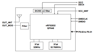
  • This is the correct datasheet for the EYSHCNZWZ. The block diagram (below) shows a LFXTAL of 32.768KHz.

    I can't seem to find any detail on this XTALs and the accuracy. Can I assume it is just as good as the one on the DK and use those same settings?

  • Hello,

    Sorry. You are correct. I found the datasheet to the EYSHSNZWZ, not EYSHCNZWZ

    I can't find any information on the LFXTAL in that datasheet either. You can check with the vendor or producer of the module. They should know.

    I found a hint, though. On page 9 in the datasheet that you sent, there is a section regarding ANT:

    " *2 ANT specification requires +/-50ppm accuracy for 32.768kHz clock. the internal 32.768kHz crystal does not meet to +/-50ppm over the whole recommended operation temperature range. "

    So it probably means that the XTAL is in the field around 50ppm, but not below that value for all temperatures. It is probably not 20ppm, which is the default setting in the SDK examples. Try to just increase (/decrease) the accuracy from 20ppm to 50ppm or 75ppm in sdk_config.h.

    Just to be sure, you power up the chip the same way when you program it and when you don't?

    Best regards,

    Edvin

  • I will contact Taiyo Yuden for the LFXTAL specs. 

    Power is the same when programming or not.

    I also have some issues with SPI not getting the correct data at 8MHz, but it is working at 1MHz. When I connect the JLink debugger, 8MHz is working. Probably the same clock configuration issue?

  • JenR said:
    I also have some issues with SPI not getting the correct data at 8MHz, but it is working at 1MHz. When I connect the JLink debugger, 8MHz is working. Probably the same clock configuration issue?

     To be honest, that doesn't sound very likely. If you are the SPI master, you are the one generating the clock signal. It shouldn't matter whether it is a bit off. If you are the slave, you get the clk signal from the master, so that should be fine too. Either way, 1MHz is too fast for the 32kHz. It is not that clock that deals with SPI.

    It may be that you have too long SPI wires. Things start to act weird when you are around 4MHz. Unless it is a short PCB trace, 8MHz sounds a bit too fast.

    Best regards,

    Edvin

Reply
  • JenR said:
    I also have some issues with SPI not getting the correct data at 8MHz, but it is working at 1MHz. When I connect the JLink debugger, 8MHz is working. Probably the same clock configuration issue?

     To be honest, that doesn't sound very likely. If you are the SPI master, you are the one generating the clock signal. It shouldn't matter whether it is a bit off. If you are the slave, you get the clk signal from the master, so that should be fine too. Either way, 1MHz is too fast for the 32kHz. It is not that clock that deals with SPI.

    It may be that you have too long SPI wires. Things start to act weird when you are around 4MHz. Unless it is a short PCB trace, 8MHz sounds a bit too fast.

    Best regards,

    Edvin

Children
No Data
Related