This post is older than 2 years and might not be relevant anymore
More Info: Consider searching for newer posts

Problem: Enable Disable UART, ADC peripherals?

Hello to all,

I am using nRF52840 with SES SDK15.0 version. My device is goes into sleep mode after sending data to server. But when woke up device for first reading data successfully send and it will goes into sleep mode. After few minute it wakeup that time not able to ON proper ADC and UART functionality. Also i am struggling for debug because not showing any error it shows only unknown fuction at 0x000978 like this. 

Please help me how i can fix this issue, here is my bellow function for sleep mode:

void stop_adc()
{

    nrf_drv_timer_disable(&m_timer);
    nrf_drv_timer_uninit(&m_timer);
    nrf_drv_ppi_channel_disable(m_ppi_channel);
    nrf_drv_ppi_uninit();
//    NRF_SAADC->TASKS_STOP = 1;
    nrf_drv_saadc_uninit();
}

void sleep_mode_enter()
{
  uint32_t err_code;
  NRF_LOG_INFO("Sleep mode Enter");
  stop_adc();
  err_code = app_uart_close();
  APP_ERROR_CHECK(err_code);                          
//  NRF_LOG_INFO("UART close: %d", err_code);
//  stop_BLE();
}

void startMeasuring_reading()
{
   NRF_LOG_INFO("Measurement started");
   int dataCounter=0;
   int flag = 0;
   int flag2 = -10;
   int flag3 = 0;
   int NextChannelCounter=0;
   int notificationConter = 0;
   int connectionflag = 0;
   uint8_t channel_number = -1;
   bool START_SENDING = false;
   uart_init();
   saadc_sampling_event_init();
   saadc_sampling_event_enable();
}

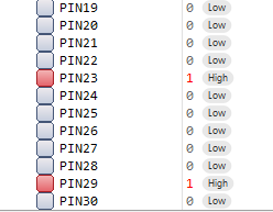
Also one another thing is i am trying to HIGH and LOW GPIOP0.23 and P0.29 but not able to HIGH this pin why it so. Is it any configuration for access GPIO of nRF52840 DK.

nrf_gpio_cfg_output(23);

nrf_gpio_pin_set(23); // High pin

Is the above code is correct please suggest me proper way or provide program snippet for the above both issues.

Thanks in advanced...

Parents
  • 1)

    "Also i am struggling for debug because not showing any error it shows only unknown fuction at 0x000978 like this." 
    - like what?

    We need the definitions for:

    • stop_BLE();
    • uart_init();
    • saadc_sampling_event_init();
    • saadc_sampling_event_enable();

    2) 

    nrf_gpio_cfg_output(23);

    nrf_gpio_pin_set(23); 

    This should set p0.23 to logic high. 

    What is the state of the GPIO registers after you've executed the two functions above?

  • 1) stop_BLE(); means disconnect ble connection and stop advertising this call before enter sleep mode

    void stop_BLE()
    {
      uint32_t err_code;
      stop_adv = true;
        err_code = sd_ble_gap_disconnect(m_conn_handle, BLE_HCI_REMOTE_USER_TERMINATED_CONNECTION);
        APP_ERROR_CHECK(err_code);
    }
    
    static void uart_init(void)
    {
        uint32_t                     err_code;
        app_uart_comm_params_t const comm_params =
        {
            .rx_pin_no    = RX_PIN_NUMBER,//RX_PIN_NUMBER,
            .tx_pin_no    = TX_PIN_NUMBER,//TX_PIN_NUMBER,
            .rts_pin_no   = RTS_PIN_NUMBER,
            .cts_pin_no   = CTS_PIN_NUMBER,
            .flow_control = APP_UART_FLOW_CONTROL_DISABLED,
            .use_parity   = false,
    #if defined (UART_PRESENT)
            .baud_rate    = NRF_UART_BAUDRATE_115200
    #else
            .baud_rate    = NRF_UARTE_BAUDRATE_115200
    #endif
        };
    
        APP_UART_FIFO_INIT(&comm_params,
                           UART_RX_BUF_SIZE,
                           UART_TX_BUF_SIZE,
                           uart_event_handle,
                           APP_IRQ_PRIORITY_LOWEST,
                           err_code);
        APP_ERROR_CHECK(err_code);
    }
    
    void saadc_sampling_event_init(void)
    {
        ret_code_t err_code;
        err_code = nrf_drv_ppi_init();
        APP_ERROR_CHECK(err_code);
    
        nrf_drv_timer_config_t timer_config = NRF_DRV_TIMER_DEFAULT_CONFIG;
        timer_config.frequency = NRF_TIMER_FREQ_31250Hz;
        err_code = nrf_drv_timer_init(&m_timer, &timer_config, timer_handler);
        APP_ERROR_CHECK(err_code);
    
        /* setup m_timer for compare event */
        uint32_t ticks = nrf_drv_timer_us_to_ticks(&m_timer,SAADC_SAMPLE_RATE);
        nrf_drv_timer_extended_compare(&m_timer, NRF_TIMER_CC_CHANNEL0, ticks, NRF_TIMER_SHORT_COMPARE0_CLEAR_MASK, false);
        nrf_drv_timer_enable(&m_timer);
    
        uint32_t timer_compare_event_addr = nrf_drv_timer_compare_event_address_get(&m_timer, NRF_TIMER_CC_CHANNEL0);
        uint32_t saadc_sample_event_addr = nrf_drv_saadc_sample_task_get();
    
        /* setup ppi channel so that timer compare event is triggering sample task in SAADC */
        err_code = nrf_drv_ppi_channel_alloc(&m_ppi_channel);
        APP_ERROR_CHECK(err_code);
    
        err_code = nrf_drv_ppi_channel_assign(m_ppi_channel, timer_compare_event_addr, saadc_sample_event_addr);
        APP_ERROR_CHECK(err_code);
    }
    
    void saadc_sampling_event_enable(void) {
    	ret_code_t err_code = nrf_drv_ppi_channel_enable(m_ppi_channel);
    	APP_ERROR_CHECK(err_code);
    }
    

    Basically what i want to do startMeasuring_reading(); is a fun which is call every periodic interval as per requirements. When first callback come WIFi module successfully send sensor reading but when call it again second time got error in SES IDE like unknown fuction at 0x000978. Will you please provide proper way for turn off saadc , uart in sleep mode means system ON mode. It will again turn ON once  startMeasuring_reading(); call. 

    Is any issue when i call sleep_mode_enter(); in uart_event_hnandler(); callback function because when i comment this not show unknown function but program not work proper.

    2) 

    What is the state of the GPIO registers after you've executed the two functions above?

    what you are manning how i check state of GPIO registers?

    Another thing is when i use GPIO15 pin so this pin is able to set logic high but problem for p0.23. i am using PCA10056 board file.

    Thanks for reply...

    1. You won't be able to put the MCU to sleep when the debugger is connected. 

      "When first callback come WIFi module successfully send sensor reading but when call it again second time got error in SES IDE like 
      unknown fuction at 0x000978." 
      -What callback are you referring to?
    2. In a debug session in SES: View -> Registers -> Register1 -> Groups -> Turn off CPU groups, and turn on the P0 group. 
  • 1. The callback is uart_event_handle(..) When i comment uart close function then it worked but problem with again uart_init();

    2. Here is bellow screen shot of GPIO state:

    I have tried like this

    #define WIFI_PIN NRF_GPIO_PIN_MAP(0,23)
    #define SENSOR_PIN NRF_GPIO_PIN_MAP(0,29) 

    SENSOR_PIN  is working but only problem with  WIFI_PIN  i not getting high tested with multi-meter.

    Why it problem with p0.23 pin in segger when i read this resister the IDE show 1 value but not getting on multi-meter. 

    Please help me asap.

    Thanks...

Reply
  • 1. The callback is uart_event_handle(..) When i comment uart close function then it worked but problem with again uart_init();

    2. Here is bellow screen shot of GPIO state:

    I have tried like this

    #define WIFI_PIN NRF_GPIO_PIN_MAP(0,23)
    #define SENSOR_PIN NRF_GPIO_PIN_MAP(0,29) 

    SENSOR_PIN  is working but only problem with  WIFI_PIN  i not getting high tested with multi-meter.

    Why it problem with p0.23 pin in segger when i read this resister the IDE show 1 value but not getting on multi-meter. 

    Please help me asap.

    Thanks...

Children
  • 1.  "Is any issue when i call sleep_mode_enter(); in uart_event_hnandler(); callback function because when i comment this not show unknown function but program not work proper." 
    - You should never go to sleep in a callback, wait for the uart event handler to return to main and enter sleep from there.

    2. p0.23 is used with the flash chip on the DK. You need to use another gpio. See fig 1 in Connector interface

  • Thanks for reply,

    1. Now can i call sleep mode as per following way in main loop;

      for (;;) {
        if (sleep_mode_check == true){
          sleep_mode_enter();
         }
        idle_state_handle();
      }

    If i am wrong please provide proper way for call sleep mode in main loop.

    2. Ok but we have designed custom PCB so in our own PCB this pin(P0.23) should be work is it right???

    Thanks for your suggestion..!!

  • 1. I believe you stop the TIMER, SAADC, and the uart library correctly. I do not know the content of you idle_state_handle function, but it needs to contain the following function calls:
    __WFE();

    __SEV();

    __WFE();

    2. If it does not work on the custom board then there might be something wrong with the schematics/layout or the ESD diode is blown, shorting p0.23 to GND.

    What is the current consumption when p0.23 is driven "high"?

    Do you mind sharing schematics and layout files? I can view Altium, Allegro, Eagle, and raw gerber files with NC drill files. 

  • Hello,

    Sorry for very late reply, We were busy for implementing other functionality and now our application is stable. Now we have getting power consumption issue in sleep mode. Let me describe our measured consumption. 

    We have power profile kit & also digital multi-meter. We are using nRF52840DK and SDK15.0 version to built our application. 

    The measured consumption is 542uA when device is sleep mode means system ON mode.

    This consumption quite very high we should need to optimize to increase battery life because our sensor devices has battery operated. We have turn OFF all used peripheral before goes into sleep mode.

    The following way we have disabled used peripheral is it right?

    void sleep_mode_enter() {
      uint32_t err_code;
      NRF_LOG_INFO("Sleep mode Enter");
      flash_data_sending = false;
      start_measurement = false;
      if ((strcmp((char *)s_info.config_flag, "true") == 0)) { /*Check if config mode enter and called sleep_mode_enter when server request status completed */
        nrf_gpio_pin_set(WIFI_PIN); /*ON WIFI module*/
      } else {
        nrf_gpio_pin_clear(WIFI_PIN); /*OFF WiFi module*/
      }
      nrf_gpio_pin_clear(SENSOR_PIN);  // OFF Sensor
      nrf_gpio_pin_set(GREEN_LED_PIN); // OFF Green LED
      nrf_gpio_pin_set(BLUE_LED_PIN);  // OFF BLUE LED
      stop_adc();
    //  err_code = app_uart_close();
    //  APP_ERROR_CHECK(err_code);
    }
    
    void stop_adc() {
      nrf_drv_timer_disable(&m_timer);
      nrf_drv_timer_uninit(&m_timer);
      nrf_drv_ppi_channel_disable(m_ppi_channel);
      nrf_drv_ppi_uninit();
      NRF_SAADC->TASKS_STOP = 1;
      nrf_drv_saadc_uninit();
    }

    Is the above API and functions right? OR we should need to disabled other way?

    Why this current consumption getting very high in system ON mode? How i can reduced / optimize this consumption?

    We have check no any issue in our hardware. If we put device into system OFF mode that time the current consumption got 5-6 uA which is acceptable.

    Please provide some solution or right way to reduce this consumption.

    Looking forward you response...

    Thanks 

  • I have created new thread for this, so can we continue here

    Thanks for your help..!!

Related