
Hi Forum,
I have just purchased nRF52840 Dongle and trying out “Blinky” application from source SDK “nRF5_SDK_for_Thread_and_Zigbee_2.0.0_29775ac\examples\peripheral\blinky”
After compiling and building the program under Eclipse IDE, used “nRF Connect” to program the nRF52840 Dongle. I am successful in downloading and running the program using this way.
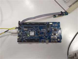
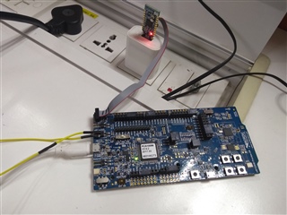
To have debugging ability, I have soldered 10-pin ARM Cortex JTAG SWD on the nRF52840 Dongle. Made the connections as shown in the pictures attached. Changed delay to 1000 ms in main.c
My problem is the downloading and debugging doesn’t work.
Interestingly I get all the messages in Eclipse like J-Link connected, GDB connected, Downloading 1748 bytes @ address 0x00001000 - Verified OK, verification is also OK but the Dongle remains in DFU boot loader mode.
No program is actually downloaded because when I power cycle the Dongle, it runs old Blinky program showing 500ms blink delay. The Eclipse Console log is attached as well for downloading.
Setup Details:
SDK: nRF5_SDK_for_Thread_and_Zigbee_2.0.0_29775ac
IDE: Eclipse
Dongle: nRF52840 dongle
Dev board: nRF52840-Preview-DK
Settings on nRF52840-Preview-DK board: Shorted P22, SW9 set on VDD
Attaching setup images and debug messages herewith.
SEGGER J-Link GDB Server V6.40 Command Line Version

JLinkARM.dll V6.40 (DLL compiled Oct 26 2018 15:06:02)

Command line: -if swd -device nRF52840_xxAA -endian little -speed 1000 -port 2331 -swoport 2332 -telnetport 2333 -vd -ir -localhostonly 1 -singlerun -strict -timeout 0 -nogui
-----GDB Server start settings-----
GDBInit file:                  none
GDB Server Listening port:     2331
SWO raw output listening port: 2332
Terminal I/O port:             2333
Accept remote connection:      localhost only
Generate logfile:              off
Verify download:               on
Init regs on start:            on
Silent mode:                   off
Single run mode:               on
Target connection timeout:     0 ms
------J-Link related settings------
J-Link Host interface:         USB
J-Link script:                 none
J-Link settings file:          none
------Target related settings------
Target device:                 nRF52840_xxAA
Target interface:              SWD
Target interface speed:        1000kHz
Target endian:                 little

Connecting to J-Link...
J-Link is connected.
Firmware: J-Link OB-SAM3U128-V2-NordicSemi compiled Jul 12 2018 11:44:41
Hardware: V1.00
S/N: 683146273
Checking target voltage...
Target voltage: 3.30 V
Listening on TCP/IP port 2331
Connecting to target...Connected to target
Waiting for GDB connection...Connected to 127.0.0.1
Reading all registers
Read 4 bytes @ address 0x00000000 (Data = 0x20000400)
Read 2 bytes @ address 0x00000000 (Data = 0x0400)
Received monitor command: speed 1000
Target interface speed set to 1000 kHz
Received monitor command: clrbp
Received monitor command: reset
Resetting target
Received monitor command: halt
Halting target CPU...
...Target halted (PC = 0x00000998)
Received monitor command: regs
R0 = 00000000, R1 = 00000000, R2 = 00000000, R3 = 00000000
R4 = 00000000, R5 = 00000000, R6 = 00000000, R7 = 00000000
R8 = 00000000, R9 = 00000000, R10= 00000000, R11= 00000000
R12= 00000000, R13= 20000400, MSP= 20000400, PSP= 00000000
R14(LR) = FFFFFFFF, R15(PC) = 00000998
XPSR 01000000, APSR 00000000, EPSR 01000000, IPSR 00000000
CFBP 00000000, CONTROL 00, FAULTMASK 00, BASEPRI 00, PRIMASK 00
Reading all registers
Read 4 bytes @ address 0x00000998 (Data = 0x47184B06)
Read 2 bytes @ address 0x00000998 (Data = 0x4B06)
Received monitor command: speed auto
Select auto target interface speed (1000 kHz)
Received monitor command: flash breakpoints 1
Flash breakpoints enabled
Received monitor command: semihosting enable
Semi-hosting enabled (Handle on BKPT)
Received monitor command: semihosting IOClient 1
Semihosting I/O set to TELNET Client
Received monitor command: SWO DisableTarget 0xFFFFFFFF
SWO disabled successfully.
Received monitor command: SWO EnableTarget 0 0 0x1 0
SWO enabled successfully.
Read 4 bytes @ address 0x00000998 (Data = 0x47184B06)
Read 2 bytes @ address 0x00000998 (Data = 0x4B06)
Downloading 1748 bytes @ address 0x00001000 - Verified OK
Downloading 8 bytes @ address 0x000016D4 - Verified OK
Downloading 112 bytes @ address 0x000016DC - Verified OK
Comparing flash   [....................] Done.
Verifying flash   [....................] Done.
Writing register (PC = 0x    12e0)
Read 4 bytes @ address 0x000012E0 (Data = 0x4A074906)
Read 2 bytes @ address 0x000012E0 (Data = 0x4906)
Received monitor command: clrbp
Received monitor command: reset
Resetting target
Received monitor command: halt
Halting target CPU...
...Target halted (PC = 0x00000998)
Received monitor command: regs
R0 = 00000000, R1 = 00000000, R2 = 00000000, R3 = 00000000
R4 = 00000000, R5 = 00000000, R6 = 00000000, R7 = 00000000
R8 = 00000000, R9 = 00000000, R10= 00000000, R11= 00000000
R12= 00000000, R13= 20000400, MSP= 20000400, PSP= 00000000
R14(LR) = FFFFFFFF, R15(PC) = 00000998
XPSR 01000000, APSR 00000000, EPSR 01000000, IPSR 00000000
CFBP 00000000, CONTROL 00, FAULTMASK 00, BASEPRI 00, PRIMASK 00
Reading all registers
Read 4 bytes @ address 0x00000998 (Data = 0x47184B06)
Read 2 bytes @ address 0x00000998 (Data = 0x4B06)
Starting target CPU...
Any kind of help is most welcome.
Thanks,
Rajendra

