This post is older than 2 years and might not be relevant anymore
More Info: Consider searching for newer posts

nrf52832 SPIM0 events stopped stuck problem

Hi,

I want to read a IC register over SPI.

This is msp430 code,it works. Just

CS low

write address

write 0x00

CS high

void bmx_spi_read(uint8_t addr,uint8_t *data)
{
    P1OUT &= ~BMX_cs;
    __delay_cycles(100);

    while(!(IFG2&UCB0TXIFG));
    UCB0TXBUF = addr;
    while(!(IFG2&UCB0TXIFG));
    UCB0TXBUF = 0x00;

    while(!(IFG2&UCB0RXIFG)); 
    *data = UCB0RXBUF;

    __delay_cycles(100);
    P1OUT |= BMX_cs;

}


I use SPIM, this is initialization

  NRF_SPIM0->PSEL.SCK  = bmx_sck;
  NRF_SPIM0->PSEL.MOSI = bmx_mosi;
  NRF_SPIM0->PSEL.MISO = bmx_miso;

  NRF_SPIM0->FREQUENCY = SPIM_FREQUENCY_FREQUENCY_M1 << SPIM_FREQUENCY_FREQUENCY_Pos;

  NRF_SPIM0-> ENABLE = SPIM_ENABLE_ENABLE_Enabled << SPIM_ENABLE_ENABLE_Pos;
  uint8_t bmx_id=0;
  
  NRF_GPIO->OUTCLR = (1UL << bmx_cs1);
  dly = 1000;
  while(dly--);
  bmx_id=spi_read(0x00);
  dly = 1000;
  while(dly--);
  NRF_GPIO->OUTSET = (1UL << bmx_cs1);

this is spi read function

uint8_t spi_read(uint8_t addr)
{

  uint8_t tx_buf[2];
  uint8_t rx_buf[1];

  NRF_SPIM0->SHORTS = SPIM_SHORTS_END_START_Msk;

  tx_buf[0] = addr;
  tx_buf[1] = 0x00;
  NRF_SPIM0->TXD.MAXCNT = sizeof(tx_buf);
  NRF_SPIM0->TXD.PTR = (uint32_t)&tx_buf[0];

  NRF_SPIM0->RXD.MAXCNT = 1;
  NRF_SPIM0->RXD.PTR = (uint32_t)&rx_buf[0];

  NRF_SPIM0->EVENTS_STOPPED = 0;
  NRF_SPIM0->TASKS_START = 1;
  while (NRF_SPIM0->EVENTS_STOPPED == 0);

  return rx_buf[0];

}

I test it debug mode and the code stucks at while (NRF_SPIM0->EVENTS_STOPPED == 0); line

For generate 16 clock cycles, i need to write extra 0x00 bytes in msp430. 

TX and RX operations works simultaneously like MSP430? 

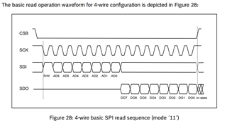
Read diagram should be like below.

Parents
  • I read datasheet of SPIM peripheral again. 

    I changed read function code as

    uint8_t spi_read(uint8_t addr)
    {
    
      uint8_t tx_buf[2];
      uint8_t rx_buf[2];
    
      // SHORT ayarı yapılacak
      NRF_SPIM0->SHORTS = SPIM_SHORTS_END_START_Msk;
    
      tx_buf[0] = addr;
      tx_buf[1] = 0x00;
      NRF_SPIM0->TXD.MAXCNT = sizeof(tx_buf);
      NRF_SPIM0->TXD.PTR = (uint32_t)&tx_buf[0];
    
      NRF_SPIM0->RXD.MAXCNT = sizeof(rx_buf);
      NRF_SPIM0->RXD.PTR = (uint32_t)&rx_buf[0];
    
      
      NRF_SPIM0->TASKS_START = 1;
      while(NRF_SPIM0->EVENTS_ENDTX == 0);
      while(NRF_SPIM0->EVENTS_ENDRX == 0);
      while(NRF_SPIM0->EVENTS_END == 0);
      NRF_SPIM0->TASKS_STOP = 1;
      while (NRF_SPIM0->EVENTS_STOPPED == 0);
      return rx_buf[1];
    
    }
     

    Now, there is no stuck in events_stopped line. 

    Also, datasheet says : "The SPI master is a synchronous interface, and for every byte that is sent, a different byte will be received at
    the same time" this means simultaneously  as answer for my question. 

    But, i'm still wrong value,i get 0x00 rather than 0xFA. 

    Can anyone verify the code according to spi transfer diagram?

    Best Regards

    Berker

  • Hi

    I don't see why this shouldn't work. You don't need all those while loops though. while(NRF_SPIM0->EVENTS_END == 0) should enough in your case.

    If you always get 0x00 it could a HW issue. Maybe you are using the wrong pins, the pins are shorted to ground, your slave isn't powered on or not started, etc. 

    If you have a logic analyzer or an oscilloscope it could be useful to see what goes on on the SPI bus. 

  • Hi 

    Slave device BMX055 IMU. The problem looks like pcb trace or SPI peripheral registers related. 

    MISO from device

    There is a strange voltage on MISO line. I'm sure MOSI is correct. 

    It should be byte1: 0x00 byte2:11111010 

    but byte2:????1?1?, there are uncertain values.

    I didn't set SPI pins input or output,only set ChipSelect as output. 

    What is the problem? Is it pcb trace related or what?

    Best Regards

Reply
  • Hi 

    Slave device BMX055 IMU. The problem looks like pcb trace or SPI peripheral registers related. 

    MISO from device

    There is a strange voltage on MISO line. I'm sure MOSI is correct. 

    It should be byte1: 0x00 byte2:11111010 

    but byte2:????1?1?, there are uncertain values.

    I didn't set SPI pins input or output,only set ChipSelect as output. 

    What is the problem? Is it pcb trace related or what?

    Best Regards

Children
  • BMX055 has 3 sensors inside. Acceleremoter,Gyro,Magnetometer. There are 3 different Chip Select. 

    My mistake, Gyro CS was LOW!.(This means both ACC and GYRO was active)

    Expected response for ACC:     1111 1010

    Expected response for GYRO:  0000 1111

    Result on MISO                         ???? 1?1?

    If 2 sensors drive different bit values at the same, data collision occured and this results avarage value on MISO line. 

    I set CS high at the start of the code:

    NRF_GPIO->OUTSET = (1UL << bmx_cs2);

    This maybe helpful for others.

    Thanks.


Related