This post is older than 2 years and might not be relevant anymore
More Info: Consider searching for newer posts

Current consumption for bluetooth mesh using PCA10056

Hi, 

I'm currently doing a current consumption test for bluetooth mesh using PCA10056. I want to label the plot like the ones in Online Power Profiler, but it turns out I'm really unfamiliar with what states bluetooth mesh has (for example, Pre-processing, Radio TX, Radio switch ...). Are there any documents that I can read to have a better understanding of this? 

I just started learning the bluetooth related stuff, I'm sorry if the question sounds stupid. Hoping you guys can help me with that. 

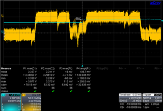
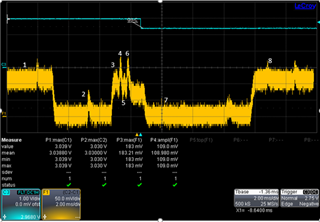
Here attached one plot I got, can someone tell me if it looks reasonable or not? Thanks in advance

Parents
  • I am afraid that we do not have any online power profiler for Bluetooth Mesh node.

    A Bluetooth Mesh device will sent packets like a regular Bluetooth Low Energy device, i.e. on 3 separate channels back to back. However, as opposed to regular Bluetooth Low Energy devices, a Bluetooth Mesh node will usually keep the Radio in RX mode the majority of the time. So, if you plot the current consumption you will have a constant current draw corresponding to the NRF52840's Radio RX current. 

    I cant see any current numbers in the attached plot.

    Best regards

    Bjørn

  • Hi,

    Thank you for the reply.

    I actually redid the test last week, I'm using nRF52840, with DCDC off. Here's the plot and data I got. I noticed that when I probe the server board using the light_switch mesh example, I only had one Tx-Rx cycle (instead of 3 as you mentioned). Not sure what's the reason for that. Could you take a look at the graph and the data, and please let me know if I'm doing anything wrong? Thank you thank you.


    State

    Time[ms]

    Current[mA]

    1

    Always radio on


    12

    2

    Pre-processing and Standby

    4

    4

    3

    Radio preparation

    0.6

    10

    4

    TX

    0.4

    15

    5

    TX to RX transition

    0.6

    10

    6

    RX

    0.2

    14

    7

    Post-processing and Standby

    7

    0

    8

    Always radio on


    12

Reply
  • Hi,

    Thank you for the reply.

    I actually redid the test last week, I'm using nRF52840, with DCDC off. Here's the plot and data I got. I noticed that when I probe the server board using the light_switch mesh example, I only had one Tx-Rx cycle (instead of 3 as you mentioned). Not sure what's the reason for that. Could you take a look at the graph and the data, and please let me know if I'm doing anything wrong? Thank you thank you.


    State

    Time[ms]

    Current[mA]

    1

    Always radio on


    12

    2

    Pre-processing and Standby

    4

    4

    3

    Radio preparation

    0.6

    10

    4

    TX

    0.4

    15

    5

    TX to RX transition

    0.6

    10

    6

    RX

    0.2

    14

    7

    Post-processing and Standby

    7

    0

    8

    Always radio on


    12

Children
Related