This post is older than 2 years and might not be relevant anymore
More Info: Consider searching for newer posts

SPI Master pin set and clear

I am trying to run the SPI code on an NRF52382 based custom board. I am using the NRF 52 DK,  Keil uVision 5.0 , SDK 15.2.

I cannot set and clear the SPI relevant pins on my custom board as gpios. The pins I am using are:
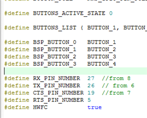
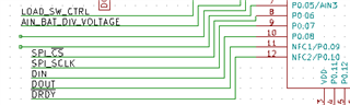
SPI_SS_PIN = P0.6
SPI_MISO_PIN = P0.8
SPI_MOSI_PIN = P0.9
SPI_SCK_PIN = P0.7 

and the schematic showing these pins is: 

I was successfully able to toggle all four pins above, (as well as the RESET P0.21) as GPIOs after I did following: 

1. went to sdk_config.h and changed  NRF_LOG_BACKEND_UART_TX_PIN    to pin 5 instead of 6

2. went to OPTIONS FOR TARGET -> C/C++ -> Preprocessor Symbols -> Define and added " CONFIG_NFCT_PINS_AS_GPIOS" after nrf52382.... and removed the line " CONFIG_GPIO_AS_PINRESET"

But as soon as I run the SPI example code in SDK15 I am unable to toggle these pins and use them as gpios. Especially the SPI_SS_PIN which is pin 6, as soon as I run the SPI code this pin fixes to high value and will not clear/go low.  

My thinking is there something wrong with the way the SPI example configures the spi relevant pins? 

https://devzone.nordicsemi.com/f/nordic-q-a/18546/gpio-not-set-or-clear-with-spi-code this guy seemed to have had the same problem running SPI and with the CS pin...

Thank you! 

Parents
  • Depends perhaps on when you are doing a set/clear test; try setting the SPI_SS_PIN pin to NRF_DRV_SPI_PIN_NOT_USED before initialising the spi, and see if that allows manually set/clear of the /CS pin. Note in this case a manual configuration of the pin to Output must be made as the SPI driver is no longer controlling the pin. The reason for doing this is to ensure nothing else is interfering with the pin; the spi driver does not control the /CS pin with hardware spi but instead runs a set or clear instruction encapsulating the hardware spi transmission. That means the user can just as easily do the set/clear before and after the spi transfer, or allow the handler to do it as in your case.

    Other devices have hardware control over the /CS pin (similar to SCK, MOSI and MISO), but not the nRF52832.

    Also you are probably aware, but if you are testing on a DK then pin 6 is connected in hardware ..

  • Updated:   Now I am configuring the CS pin after I initialize the SPI and it seems to work because the pin goes down to 0.7 V from the earlier Vdd HIGH 3.3V. However, even though the voltage value reduced I do not think this means the SPI_SS_PIN is LOW because the LOW value on my board is typically in millivolts. 

    I am thinking the 0.7V for the CS pin is a floating value. And I do not get why I cannot clear the SPI_SS_PIN?  
    Could this be because the SPI_SS_PIN needs to have a falling edge (and not clear 0) for the SPI peripheral device to be connected? 

    Thanks again

  • Yes I did do that. I set it to NOT_USED in the nrf_drv_spi.h file before I configured it as high low drive. 

    There is another thing I tried after that. I tried enabling my peripheral with pin 6 as a gpio instead of as the SPI slave select pin. I set spi.config.ss_pin to NRF_DRV_SPI_PIN_NOT_USED. And then I did not set Pin 6 to spi.config.ss_pin. Instead I set Pin 6 to LOW as a simple GPIO and said that SPI_SS_PIN is not used (there is no hardware pin connected to SS). 

    But surprisingly I got the same result. 
    The peripheral I am using is the ADS1220 (analog to digital conv). Maybe it sets its slave select to 0.7 V whenever it is provided clock and there is sth withe the ADC?  

  • I have used the ADS1220, albeit on a Dialog BLE radio, and not had any issues; the /CS worst-case leakage on that device is only 10uA and so there must be some other hardware or software item interfering with operation of the pin. Since that only happens with your spi code enabled, either there is something still in contention in the code or maybe there is a fault on the ADS1220; can you try a second board, just in case? Maybe also post the spi init code ..

  • Here is my SPI code : 

    I hope the images are visible in a comment...
    Thank you for your help! I appreciate it

  • Ah, I think your code will not work as NULL for tx buffer and length is not valid and will cause an assert. I imagine that setting a command byte but not transmitting it was not what you intended; here is a typical invocation:

    Compare this with the nrf_drv_spi_transfer() you are using in your code image, and you will note that the transmit command and length are both NULL, or zero, which is not acceptable.

    Also, just as an aside, what pins are the LEDs on?

  • This is the assert trap:

Reply
  • This is the assert trap:

Children
  •  So I fixed this ^ that you pointed out. I now initialize m_tx_buf [0] = 0x08 and rest of m_tx_buf array to 0 ; and then do nrf_drv_spi_transfer(&spi, m_tx_buf, tx_length, m_rx_buf, rx_length). But the problem is same as before. I also noticed that there are NO LEDs on my custom PCB device that I am programming so I commented out all the BSP and LED relevant code and run the program again. But that did not fix the issue either. If I use P0.6 as a simple GPIO in the same project with the SPI parts commented out, it works fine and sets to clear if I want to. 

    I even redefiened " #define NRF_DRV_SPI_PIN_NOT_USED  0x00   from 0xFF" in the nrf_drv_spi header file to make the default spi_not_used value 0 but that did not work either. 

    Another thing that I noticed: Even though I am not initializing, or using the DRDY pin ((P0.10) on my nrf) anywhere in the entire project, just it being connected to the DRDY on the ADS1220 (the ADC) chip on my PCB makes it go to 3.3V (Vdd) instead of a float value (as it should be if it is unused and unconfigured).  Also, when I set the CS pin to HIGH it goes up to 2.6 V (not upto 3.3V like the other pins do when they are HIGH). Do these things say sth about how the ADC is working? 

    Thank you once again. 

    Since I am working with a custom PCB changing the CS pin would mean making another layout and board. Would you recommend I short pin 6 to pin 5 externally on the nrf52 on the PCB and then use pin 5 to control CS? When you were using ADS1220 , did you get problems with its CS pin at all, and were you externally tying it down to DGND? I remember running SPI on another ADS1220 chip using nrf52 DK first and was getting problems running SPI master successfully earlier as well. This is why I shifted to the custom PCB.  

  • On the ADS1220 the dedicated /DRDY signal is not open-drain and will drive to a high level (3.3 volts) except when pulsing low to indicate data ready; therefore P0.10 will have 3.3 volts as you observe (ie correct behavior).

    The pin 6 issues you see imply either a short to another pin on the ADS1220 or pin 6 being used somewhere else in the code on another nRF52 peripheral. It is also possible (unlikely) that the ADS1220 GND is sitting at +1.0 volts and the schottky clamp diodes in the ADS1220 therefore hold pin 6 at 0.7 volts. Are you switching the voltage supplies to the ADS1220 with port pins, or have any series resistance in the GND line? Note 2.7 volts + 0.7 volts is also suspiciously close to 3.3 volts, though that may be a red herring. Connecting pin 5 to pin 6 would be a hack and may hide the true issue you are looking for.

    The ADS1220 has no requirement for any pull-up or pull-down resistors on any of the SPI lines, including /CS and /DRDY, and I have never had any issues in driving these lines. I suggest you post the actual code text of the spi code init and handler you are using with an Insert Code box. I will look out settings I have used on this chip and post them later this weekend. Pins 7, 10, and 11 should be at 3.3 volts. Pins 1,2,3,4,6 and 17 should all be at Gnd (0v wrt nRF52) unless you are doing something special.

    One last comment, have you left any serial uart code enabled? The default for the PCA10040 which I think you started with has the following conflict with pin P0.6:

  • Yes, some of my serial uart is enabled. I need to read data from my ADC and send it to the computer via the uart (i.e. I am using NRF_LOG_INFO ). I did change the UART_TX pin number from 6 to 5 in the sdk_config.h file before I even started. That should be okay since pin 5 is unused on my custom board. I am sure pin 6 is not being used anywhere else in the sdk_config.h of my project. Where else should I be checking to make sure where else it is being used? To stop its UART_TX functionality, is removing it from the sdk file enough? 
    P.S. I tried removing all NRF_LOG and LOG initialization code (all the data logging code) in my main file and running the code but the problem persists. 

    My ADS1220 pins are: 
    pin 11 - 3.3V, pin 10 at 5V,    
    Pin 6 and 7 are both at 1.8V.  All the rest of the pins on ADS1220 are as you said should be. 


    Here is my code. What I get from this code is FATAL ERROR on my putty terminal, and I believe the values of the RX and TX registers are showing the addresses of some registers, not data because although these values are persistent (do not change/aren't garbage), they are not corresponding to my voltage data input. 

  • See .\nRF5_SDK_15.2.0_9412b96\components\boards/pca10040.h for the serial port pin definitions using pin 6.

    Fatal Error .. is that coming from an assert()?

    I would suggest moving the following code until after the loop in main; ie logging only when spi_xfer_done is set otherwise the huge delay in that interrupt handler can cause all sorts of issues which will cloud what is going on:

  • I do not think the FATAL ERROR is because of sending NULL in the spi_transfer() function. I am using the code below (sending a full tx_buf without any NULL but I still get a fatal error). 

    I changed the UART _TX pin from 6 to 26 in the sdk_config.h file and changed the TX_PIN_NUMBER and RX_PIN_NUMBER in the pca10040.h file. But that does not fix the problem. 


    I did manage to pull down PIN 6 (my CS pin) as a GPIO by configuring it in high drive. Pin 6 goes down to 150mV which is a logical 0. But I am still worried because the program still gives me a fatal error and the RX_BUF seems to read a fixed address instead of taking in data from any input.   My rx_buf always contains an int value of "20000006 " no matter what the input. And the tx_buf prints out on the NRF_LOG and int value of "20000002"  even though I am sending "08000000".  I do not understand where the fatal error comes from and why my rx_buf and tx_buf always read these values even when there is no reference to these in the codes? I am using they echo some address... ?

    I am inserting my code here again for reference. 

    Q1: Am I missing some other file where I should disable the other uses of pin P0.6? 
    Q2: I think that forcing the pin 6 down (though successful when I config p6 as high drive) is causing the fatal error. The SPI transfer is not complete or sucessful because my tx and rx buffers read a fixed register value/address ...?
    Q3: Did you use Mode 1 or Mode 0 in your SPI code for ADS1220?