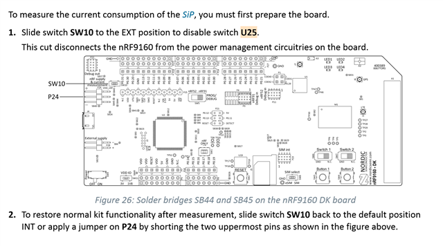
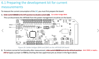
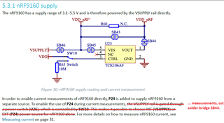
I looked at the nRF91_DK_User_Guide and it is very confusing to understand how to set up the board for current measurements. The figure says to solder SB44 and SB45 but the text doesn't. In fact, the text refers to the figure talking about shorting P24, which the figure does not illustrate. If I switch SW10 to Ext and I supply 5V on P28 it doesn't work at all. If I switch SW10 to Int but I provide power using P28 the system does work. Should I be shorting SB44 and SB45? I think the documentation needs to be improved here.


