This post is older than 2 years and might not be relevant anymore
More Info: Consider searching for newer posts

nrf52 Custom Board

Hi, 

im trying to turn on LEDs on my custom nRF52 board. Im using LEDs on 13,14,15 pins. I config pins in pca10040.h to my LED pins, but they dont work. Also if i try to put external LEDs on nrf52 DK and config them as output and high drive they also dont work. What i am doing wrong? I also noticed 2 components between LED and nrf52 DK, what are this 2 components for?

Thanks for help.

Parents
  • Hi.

    Which SDK are you using?


    I config pins in pca10040.h to my LED pins, but they dont work

     Which defines have you edited? Could you post some code?

    Also if i try to put external LEDs on nrf52 DK and config them as output and high drive they also dont work. What i am doing wrong

     Could you post some code?

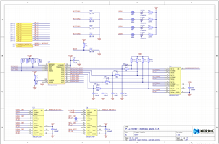
    I also noticed 2 components between LED and nrf52 DK, what are this 2 components for?

     Which components are you talking about?

    Best regards,

    Andreas

Reply
  • Hi.

    Which SDK are you using?


    I config pins in pca10040.h to my LED pins, but they dont work

     Which defines have you edited? Could you post some code?

    Also if i try to put external LEDs on nrf52 DK and config them as output and high drive they also dont work. What i am doing wrong

     Could you post some code?

    I also noticed 2 components between LED and nrf52 DK, what are this 2 components for?

     Which components are you talking about?

    Best regards,

    Andreas

Children
  • int main(void)
    {
        /* Configure board. */
    
    //    bsp_board_init(BSP_INIT_LEDS);
        nrf_gpio_cfg(
            13  ,
            NRF_GPIO_PIN_DIR_OUTPUT,
            NRF_GPIO_PIN_INPUT_DISCONNECT,
            NRF_GPIO_PIN_NOPULL,
            NRF_GPIO_PIN_H0H1,
            NRF_GPIO_PIN_NOSENSE);


        /* Toggle LEDs. */
        while (true)
        {
    //        for (int i = 0; i < LEDS_NUMBER; i++)
    //        {
    //            bsp_board_led_invert(i);
    //            nrf_delay_ms(500);
    //        }
                nrf_gpio_port_out_write(13 ,true);
                nrf_delay_ms(300);
                nrf_gpio_port_out_write(13 ,false);
               
        }
    }

    Here is code from blinky example - testing external LEDs on nRF52 DK.

    Here is elements between LEDs and buttons.

    #include "nrf_gpio.h"
    
    // LEDs definitions for PCA10040
    #define LEDS_NUMBER    4
    
    //#define LED_START      17
    #define LED_1          22
    #define LED_2          18
    #define LED_3          19
    #define LED_4          20
    //#define LED_STOP       20
    
    #define LEDS_ACTIVE_STATE 0
    
    #define LEDS_INV_MASK  LEDS_MASK
    
    #define LEDS_LIST { LED_1, LED_2, LED_3, LED_4 }
    
    #define BSP_LED_0      LED_1
    #define BSP_LED_1      LED_2
    #define BSP_LED_2      LED_3
    #define BSP_LED_3      LED_4
    
    #define BUTTONS_NUMBER 4

    pca10040.h config LED_1 to pin 22 for external LED on nRF52 DK on ble_app_blinky - nothing changed in main.c

    Thanks for replay

  • Hi.

    The first code snippet:

    I don't think that you have the right configuration, try this one:

    __STATIC_INLINE void nrf_gpio_cfg_output(uint32_t pin_number)
    {
        nrf_gpio_cfg(
            pin_number,
            NRF_GPIO_PIN_DIR_OUTPUT,
            NRF_GPIO_PIN_INPUT_DISCONNECT,
            NRF_GPIO_PIN_NOPULL,
            NRF_GPIO_PIN_S0S1,
            NRF_GPIO_PIN_NOSENSE);
    }
    

    You can configure a LED by calling nrf_gpio_cfg_output(uint32_t pin_number).

    Also, have you tried to use nrf_drv_gpiote_out_set(13) to toggle the pin?

    Schematic:

    The reason for the resistance before the LED is so that it does not burn/overheat. The solder-bridge I think is there so that you can solder on a PIN if you like.

    The last code snippet:

    Why have you commented out LED_START / LED_STOP? You also have not defined the LEDS with your pin number as far as I can tell.

    Best regards,

    Andreas

  • Im using RGB LED, that's why i set to H0H1. LED_START and LED_STOP I commented becouse i dont need them, Do I need define LED_1 pin number same pin as number in nrf_gpio_cfg ?  Those 2 codes i tried one with bsp_board_init(BSP_INIT_LEDS) - code example when LED_1 is set to pin22 and other i tried with only nrf_gpio_cfg without  bsp_board_init function.

  • Hi.

    Kev said:
    LED_START and LED_STOP I commented becouse i dont need them

     Sorry about this, I did not notice that.

    Kev said:
    Do I need define LED_1 pin number same pin as number in nrf_gpio_cfg

     Yes, when you use the bsp library, you have to have the same pin number in your pca10040.h file as the one you configure in your main.c file.

    Best regards,

    Andreas

  • Hello. I am also wondering how to change pin number in this example. For example, how should I do if I want to use only LED1 in this example? Should I call the nrf_gpio_cfg_output(uint32_t pin_number) as well? What is the pin number in this case? I'm glad if you could tell me more detail. Thank you.

Related