This post is older than 2 years and might not be relevant anymore
More Info: Consider searching for newer posts

nrf52 Custom Board

Hi, 

im trying to turn on LEDs on my custom nRF52 board. Im using LEDs on 13,14,15 pins. I config pins in pca10040.h to my LED pins, but they dont work. Also if i try to put external LEDs on nrf52 DK and config them as output and high drive they also dont work. What i am doing wrong? I also noticed 2 components between LED and nrf52 DK, what are this 2 components for?

Thanks for help.

Parents
  • Hi.

    Which SDK are you using?


    I config pins in pca10040.h to my LED pins, but they dont work

     Which defines have you edited? Could you post some code?

    Also if i try to put external LEDs on nrf52 DK and config them as output and high drive they also dont work. What i am doing wrong

     Could you post some code?

    I also noticed 2 components between LED and nrf52 DK, what are this 2 components for?

     Which components are you talking about?

    Best regards,

    Andreas

  • int main(void)
    {
        /* Configure board. */
    
    //    bsp_board_init(BSP_INIT_LEDS);
        nrf_gpio_cfg(
            13  ,
            NRF_GPIO_PIN_DIR_OUTPUT,
            NRF_GPIO_PIN_INPUT_DISCONNECT,
            NRF_GPIO_PIN_NOPULL,
            NRF_GPIO_PIN_H0H1,
            NRF_GPIO_PIN_NOSENSE);


        /* Toggle LEDs. */
        while (true)
        {
    //        for (int i = 0; i < LEDS_NUMBER; i++)
    //        {
    //            bsp_board_led_invert(i);
    //            nrf_delay_ms(500);
    //        }
                nrf_gpio_port_out_write(13 ,true);
                nrf_delay_ms(300);
                nrf_gpio_port_out_write(13 ,false);
               
        }
    }

    Here is code from blinky example - testing external LEDs on nRF52 DK.

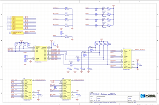
    Here is elements between LEDs and buttons.

    #include "nrf_gpio.h"
    
    // LEDs definitions for PCA10040
    #define LEDS_NUMBER    4
    
    //#define LED_START      17
    #define LED_1          22
    #define LED_2          18
    #define LED_3          19
    #define LED_4          20
    //#define LED_STOP       20
    
    #define LEDS_ACTIVE_STATE 0
    
    #define LEDS_INV_MASK  LEDS_MASK
    
    #define LEDS_LIST { LED_1, LED_2, LED_3, LED_4 }
    
    #define BSP_LED_0      LED_1
    #define BSP_LED_1      LED_2
    #define BSP_LED_2      LED_3
    #define BSP_LED_3      LED_4
    
    #define BUTTONS_NUMBER 4

    pca10040.h config LED_1 to pin 22 for external LED on nRF52 DK on ble_app_blinky - nothing changed in main.c

    Thanks for replay

  • Hi.

    The first code snippet:

    I don't think that you have the right configuration, try this one:

    __STATIC_INLINE void nrf_gpio_cfg_output(uint32_t pin_number)
    {
        nrf_gpio_cfg(
            pin_number,
            NRF_GPIO_PIN_DIR_OUTPUT,
            NRF_GPIO_PIN_INPUT_DISCONNECT,
            NRF_GPIO_PIN_NOPULL,
            NRF_GPIO_PIN_S0S1,
            NRF_GPIO_PIN_NOSENSE);
    }
    

    You can configure a LED by calling nrf_gpio_cfg_output(uint32_t pin_number).

    Also, have you tried to use nrf_drv_gpiote_out_set(13) to toggle the pin?

    Schematic:

    The reason for the resistance before the LED is so that it does not burn/overheat. The solder-bridge I think is there so that you can solder on a PIN if you like.

    The last code snippet:

    Why have you commented out LED_START / LED_STOP? You also have not defined the LEDS with your pin number as far as I can tell.

    Best regards,

    Andreas

Reply
  • Hi.

    The first code snippet:

    I don't think that you have the right configuration, try this one:

    __STATIC_INLINE void nrf_gpio_cfg_output(uint32_t pin_number)
    {
        nrf_gpio_cfg(
            pin_number,
            NRF_GPIO_PIN_DIR_OUTPUT,
            NRF_GPIO_PIN_INPUT_DISCONNECT,
            NRF_GPIO_PIN_NOPULL,
            NRF_GPIO_PIN_S0S1,
            NRF_GPIO_PIN_NOSENSE);
    }
    

    You can configure a LED by calling nrf_gpio_cfg_output(uint32_t pin_number).

    Also, have you tried to use nrf_drv_gpiote_out_set(13) to toggle the pin?

    Schematic:

    The reason for the resistance before the LED is so that it does not burn/overheat. The solder-bridge I think is there so that you can solder on a PIN if you like.

    The last code snippet:

    Why have you commented out LED_START / LED_STOP? You also have not defined the LEDS with your pin number as far as I can tell.

    Best regards,

    Andreas

Children
Related