This post is older than 2 years and might not be relevant anymore
More Info: Consider searching for newer posts

Continuous Wave for nRF9160

Is there any test firmware available (or reference code) for doing total radiated power measurements?  I have the nRF9160 designed onto a PCB and we'd like to do some antenna measurements. Ideally I'd be able to put the nRF9160 into a continuous wave mode.

Thanks!

Johnny

Parents
  • Hi,


    There's a test AT command specified in the AT Command pdf at chapter 4.19, "%XRFTEST".

    You can input this command by using the example at_client, in combination with nRF connect application "LTE Link Monitor".


    Kind regards,

    Håkon

  • Thank you.  Some follow-up questions: 

    I know I can send AT commands via the LTE Link Monitor program, but could I instead use a terminal program like Putty and tap into the UART pins to the nRF9160 on the development kit? 

    Looking at the schematic for the development kit, P0.26 through P0.29 appear to be the UART comms for the AT commands.  Where on the development kit would I connect to those UART lines? Is it TPs7-10? Or is it D19 - D22?

    What I'm hoping I can do is load the at_client example onto my prototype PCB with a few modifications and send the AT commands over UART.  But I wanted to try it first on the development kit.

    Thanks again for the help!

    Johnny

  • Hi,


    Try to reset the board, not input any other AT command than this one:

    %RFTEST=2,1,0

    This should do a GPS SNR test, and provide something like this:

    ***** Booting Zephyr OS v1.13.99-ncs2 *****
    The AT host sample started
    AT%XRFTEST=2,1,0
    %XRFTEST: -103
    OK 

    Do note that you shall not test any TX without placing the device into a shielded box. This is a restricted and licensed band!

    Kind regards,

    Håkon

  • I still get the same error following your instructions.  He's a picture again, along with the output log from the nRF Connect terminal.

    /cfs-file/__key/communityserver-discussions-components-files/4/2019_2D00_03_2D00_07T14_5F00_21_5F00_18.546Z_2D00_log.txt

  • Hi Johnny,


    This one took a long time before I saw..

    I think you are missing an X in your command, it should be "AT%XRFTEST". Could you see if that one executes successfully?


    Kind regards,

    Håkon

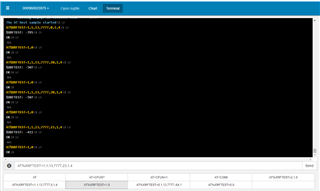
  • Awesome, you're right.  It works now.  I want to point out that some of the examples in the AT command reference document provided by Nordic omit the 'X' as well.  The picture below is from page 36 of the guide, which talks about the RF test commands.  This is probably where I got messed up.  The command is described correctly in the manual, but in the example code snippet there is no 'X.'  There are a few other examples like this too in the RF test section.

    I have one last question (hopefully). When I enter in an AT command for transmit I get a response from the module that is '%RFTEST: some number.'  According to the AT manual, dividing 'some number' by 16 is supposed to give me the power at the antenna.  When I send TX commands, the reply telling me the TX power is always negative and in the hundreds (see the nRF Connect terminal output below).  This seems to imply my power is well below -30 dBm, which can't be correct.  Am I interpreting this right, or is something else wrong?  I'm using development kits right out of the box with no modifications to them.  

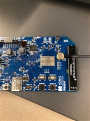
  • I connected the DK directly to my spectrum analyzer so I could measure the conducted power directly.  I am actually seeing correlation between the %XRFTEST: some number response and what I am measuring on the spectrum analyzer.  I set the output power to 0 dBm and the response was -795.  -795/16 = about -49dBm.  This is approximately what I see when I measure it.  So, my question above now changes slightly: why is the power delivered to the antenna so low when I am requesting 0 dBm?  I am plugging directly into the connector that is on the DK.

Reply
  • I connected the DK directly to my spectrum analyzer so I could measure the conducted power directly.  I am actually seeing correlation between the %XRFTEST: some number response and what I am measuring on the spectrum analyzer.  I set the output power to 0 dBm and the response was -795.  -795/16 = about -49dBm.  This is approximately what I see when I measure it.  So, my question above now changes slightly: why is the power delivered to the antenna so low when I am requesting 0 dBm?  I am plugging directly into the connector that is on the DK.

Children
Related