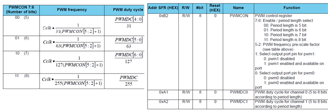
To what values should I set the PWMCON register to so that the PWM0 and PWM1 frequency is output at 20Khz with duty cycle varying between 1 to 2ms. Now specifically I am asking this after reading the data sheet because the tables mentioned are not clearing giving information. How do I decipher the table given here:
Please clearly disclose information in the data sheets. Also give an example to show how to set to particular frequency and pulse width.
Let me tell you how I decipher this as a newbie. Now CCLK is 16,000,000 for 16Mhz clock. I chose PWM0 as output so bit 0 is 1 and bit 1 is 0. Now I need to find out what PWMCON is so the formula for PWMCON for 20Khz PWM freq will be. (16000000/(255 x 20000))-1 = 160/51 -1 which is approximately 2. Hence PWMCON[5:2] will be 0010. There fore PWMCON will be 11001001 which is 0xC9. But this dint work when I put in this value for PWMCON as the servo did not rotate. Here is my code.
#include "reg24le1.h" // I/O header file for NRF24LE1
#include "hal_delay.h" // header file containing delay functions

// main function
void main()
{
int i = 0, j = 0; // loop variable
P0DIR = 0; // Port 0 as output
PWMCON = 0xc9; // enable PWM1

// infinte loop
while(1)
{
for(i= 180; i--; i > 0)
{
PWMDC0 = i ; // change duty cycle
delay_ms(10); // delay of 10 ms
}


}

}