
Hi,
I am using the nRF52840 with no soft device, and I am experiencing an issue with SPIM3 when turning on/off the ArrayList and Shortcut (EVENTS_END and TASKS_START) where the MOSI, CLK, and D/CX lines are not toggling as expected after sending a very large amount of bytes while also using PPI and the Timer Peripherals (following this guide devzone.nordicsemi.com/.../71994 Is there something that I missing here? Any help would be greatly appreciated!
Here is the sequence that I am issuing:
- Initialize SPIM3 module at 32Mbps frequency
- Set Config to Active High, Leading clock edge, MSB first
- Set Frequency to 32Mbps
- Initialize all SCK, MOSI, MISO, CSN, D/CX to High Drive
- Set SCK, MOSI, CSN, and D/CX pin to Connected
- Set MISO pin to Disconnected
- Set IFTIMING.CSNDUR = 3
- Set Shortcut to Disabled
- Set TX.D List to Disabled
- Send several 8-bit commands using SPIM3 to initialize external hardware (D/CX should be low for commands and high for data, automated with SPIM3 peripheral)
- Set TXD.PTR, TXD.MAXCNT = 1, RXD.PTR = NULL, RXD.MAXCNT = 0, DCXCNT = 1
- Enable the peripheral
- Set TASKS_START = 1
- Repeat (a) through (c) for several different commands
- Set up PPI and Timer2 so that they can be used for the long transmission, but do not enable yet
- Timer2
- Set mode to Counter
- Clear any existing Timer tasks
- Set prescaler to 0
- Set Bitmode to 16 bit
- Enable shortcut to auto-clear when the Compare0 count is reached
- Set CC[0] to 4
- Enable Compare0 Interrupt
- Set Timer2 Priority to 7 and enable Timer2IRQ through NVIC
- PPI CH 5
- NRF_PPI->CH[5].EEP = (uint32_t) &NRF_SPIM3->EVENTS_END;
- NRF_PPI->CH[5].TEP = (uint32_t) &NRF_TIMER2->TASKS_COUNT;
- PPI CH 6
- NRF_PPI->CH[6].EEP = (uint32_t) &NRF_TIMER2->EVENTS_COMPARE[0];
- NRF_PPI->CH[6].TEP = (uint32_t) &NRF_SPIM3->TASKS_STOP;
- NRF_PPI->FORK[6].TEP = (uint32_t) &NRF_TIMER2->TASKS_STOP;
- Timer2
- Prepare ArrayList prior to long transmission
- ArrayList has this structure:
#define BUFFER_SIZE 38400
#define ARRAYLIST_SIZE 5
typedef struct ArrayList
{
uint8_t buffer[BUFFER_SIZE];
} ArrayList_type;
ArrayList_type Frame_ArrayList[ARRAYLIST_SIZE];
- Use a For loop to fill every buffer entry with 0xFF for all ArrayList entries (total = 38400 * 5 = 192000 locations filled with 0xFF)
- Repeat step 2(a) through 2(c) to send one 8-bit command (D/CX should be low, automated with SPIM3 peripheral)
- Enable PPI and Timer2. Then send long transmission using EasyDMA ArrayList with PPI and Timer2 to control when to stop SPIM3
- Enable interrupt on Compare0 for Timer2
- Start the Timer
- Enable PPI for CH5 and CH6
- Enable SPIM3 shortcut for EVENTS_END/TASKS_START
- Enable TX.D List for ArrayList
- Set TXD.PTR to the first entry of the ArrayList[0]
- Set TXD.MAXCNT = BUFFERSIZE
- Set RXD.PTR = NULL and RXD.MAXCNT = 0
- Set DCXCNT = 0
- Enable the SPIM3 peripheral and set TASKS_START = 1
- The Timer is basically counting after one whole ArrayList is sent (38400 bytes transmitted). Since Timer2 CC[0] = 4, the Timer will send an interrupt after the 4th ArrayList was sent (total 38400 * 4 = 153600 bytes transmitted).
- When the Timer2 Interrupt is triggered:
- SPIM3 should be stopped and Timer2 should be stopped from the PPI
- Disable SPIM3
- Clear / disable the Timer2 Interrupt using:
NRF_TIMER2->INTENCLR = ( TIMER_INTENCLR_COMPARE0_Clear << TIMER_INTENCLR_COMPARE0_Pos ); - Clear the Timer2 tasks
- Clear the pending IRQ in NVIC for Timer2
- Disable shortcut on SPIM3
- Disable TXD.List
- Disable PPI on CH5 and CH6 using CHENCLR
- Repeat step 2(a) through 2(c) to send one 8-bit command (D/CX should be low for the command)
**Everything behaves as expected until step 8(i) where I am experiencing several issues:
- The SPIM3 module is sending out 18 clock cycles (sometimes more or less) instead of 8 even though I set TXD.MAXCNT = 1
- The MOSI line is sending out all “0” (MOSI is set up to send 0xAA), and sometimes “0” plus garbage data, and sometimes “0” plus the actual data I intended to send but offset
- The D/CX line is set to “1” even though I set up DCXCNT = 1
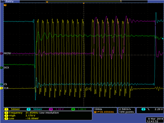
In the above image, this is an example of what I see for step 8(i). 10 clock cycles are sent, followed by 8 additional clocks with MOSI actually being correct but offset by 1 clock. D/CX is not set low as I intended.
Some interesting discoveries while debugging:
- If I use the debugger – I set a breakpoint at step 8(i)
- All the registers for SPIM3, TIMER2, and PPI are set up properly and as expected
- EVENTS_STOPPED, EVENTS_END, EVENTS_ENDTX, EVENTS_ENDRX, EVENTS_STARTED are all set to “1”
- SPIM3 shortcut and interrupt were successfully disabled and SPIM3 is currently disabled
- MAXCNT and TXD.AMOUNT = 0x9600 (as expected since we just finished sending the 38400 bytes and haven’t set up the next 8-bit command yet)
- PPI is cleared / disabled
- If I manually step through steps 2(a) through 2(c) using the debugger, then everything behaves properly and works as intended (D/CX is sent properly, the correct command is sent and no extra clocks are sent)
- All the registers for SPIM3, TIMER2, and PPI are set up properly and as expected
- If I change BUFFER_SIZE to something smaller, I tried 1000 and 5000 and 10000 instead of 38400, similar behavior is observed, but sometimes the MOSI is eventually able to send what I commanded after 10 clocks of “0” (D/CX still not responding)
- As a side question, when I set IFTIMING.CSNDUR = 3, I am expecting this to be 46.875ns, but instead I am measuring 80-90ns on the scope. I thought the calculation was 15.625ns * 3 = 46.875ns, but am I missing something?
Thanks for the help!

