This post is older than 2 years and might not be relevant anymore
More Info: Consider searching for newer posts

How to use SPI and BLE at the same time?

I need to transfer data from my ADC (analog to digital conv) on a custom made, nrf52 PCB to a mobile app via bluetooth. For this I integrated my working SPI data transfer code to a BLE_UART example (sdk 15.2). I am using the ble_nus_data_send() to send my integer data array to the Nrf app. 

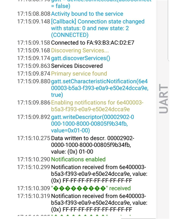
Although the project builds and flashes fine (and the device advertising and connects), the data I am getting is either nothing or a fixed array of "0xFF-FF-FF-FF-FF-FF-FF-FF-FF". What are possible problems that could be causing this? I am a little confused because I made sure the same SPI data transfer code works in a simple SPI example project.  I checked all my SPI pins seem to be working as expected in an oscilloscope. At least I am getting a proper clock signal, Master output pulses and an active low chip select while the device is connected to the app. 

Should I use timers to sample at a lower rate (if the issue could be that the SPI is working too fast for the ble)?  

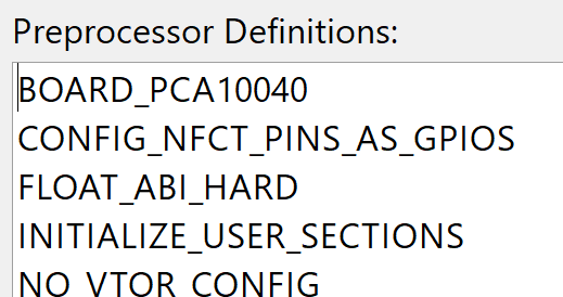
Details: So I am using MODE_1 that is compatible with my ADC, and a frequency of 1MHz, I leave the SPI irq priority to default which is 6. The pins I am using for SPI are: 7 for Clock, 8 for MOSI (master nrf output), 9 for MISO, 10 for DRDY (I do not mention or use drdy in code), 6 for Chip Select (I pull this to an active low as a GPIO instead of configuring it as spi_SS_PIN). I had to disable UART , and configure pins 9,10 as GPIO for the SPI pins to start acting normally. I can share my code if that'll help..

Parents
  • and configure pins 9,10 as GPIO

    That means nothing to me. Input? Output? MISO must be configured as an input for SPI to work properly.

  • Pin 9,10 are usually NFCT by default. So I added this to preprocessor definitions

    along with editing the UICR_config file according to instructions I read on other devzone posts for pin 9 configuration. I did this so I can use 9,10 for my SPI. 

    This is how I initialize the SPI and its pins. I tried configuring MISO after the SPI initialization as a PULLDOWN input but that did not fix the issue. 

     nrf_drv_spi_config_t spi_config = NRF_DRV_SPI_DEFAULT_CONFIG;
        spi_config.ss_pin   = SPI_SS_PIN;    // Set to UNUSED 
        spi_config.miso_pin = SPI_MISO_PIN;
        spi_config.mosi_pin = SPI_MOSI_PIN;
        spi_config.sck_pin  = SPI_SCK_PIN;
    		spi_config.frequency = NRF_DRV_SPI_FREQ_1M; 
    		spi_config.mode      = NRF_DRV_SPI_MODE_1;
        APP_ERROR_CHECK(nrf_drv_spi_init(&spi, &spi_config, spi_event_handler, NULL));


    	init_pins(); 
    //	nrf_gpio_cfg_output (SPI_MOSI_PIN);
    //	nrf_gpio_cfg_input (SPI_MISO_PIN, NRF_GPIO_PIN_NOPULL ); 
    	nrf_gpio_cfg_input (SPI_MISO_PIN, NRF_GPIO_PIN_PULLDOWN ); 


    My RTT log shows proper data once when I first open it, like an array of '1E007F' which seems like normal ADC data, but then it would go back to printing out 'FF...FFFFFF01'

Reply
  • Pin 9,10 are usually NFCT by default. So I added this to preprocessor definitions

    along with editing the UICR_config file according to instructions I read on other devzone posts for pin 9 configuration. I did this so I can use 9,10 for my SPI. 

    This is how I initialize the SPI and its pins. I tried configuring MISO after the SPI initialization as a PULLDOWN input but that did not fix the issue. 

     nrf_drv_spi_config_t spi_config = NRF_DRV_SPI_DEFAULT_CONFIG;
        spi_config.ss_pin   = SPI_SS_PIN;    // Set to UNUSED 
        spi_config.miso_pin = SPI_MISO_PIN;
        spi_config.mosi_pin = SPI_MOSI_PIN;
        spi_config.sck_pin  = SPI_SCK_PIN;
    		spi_config.frequency = NRF_DRV_SPI_FREQ_1M; 
    		spi_config.mode      = NRF_DRV_SPI_MODE_1;
        APP_ERROR_CHECK(nrf_drv_spi_init(&spi, &spi_config, spi_event_handler, NULL));


    	init_pins(); 
    //	nrf_gpio_cfg_output (SPI_MOSI_PIN);
    //	nrf_gpio_cfg_input (SPI_MISO_PIN, NRF_GPIO_PIN_NOPULL ); 
    	nrf_gpio_cfg_input (SPI_MISO_PIN, NRF_GPIO_PIN_PULLDOWN ); 


    My RTT log shows proper data once when I first open it, like an array of '1E007F' which seems like normal ADC data, but then it would go back to printing out 'FF...FFFFFF01'

Children
Related