This post is older than 2 years and might not be relevant anymore
More Info: Consider searching for newer posts

nRF51422 issues with 2nd harmonic FCC testing

Hi,

I'm using the attached circuit and we recently took our product to FCC testing and failed the 2nd harmonic because we were transmitting too much power. image description

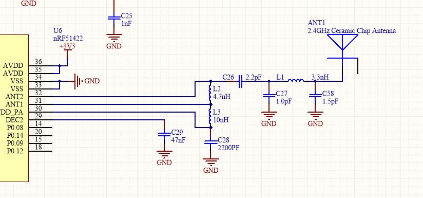
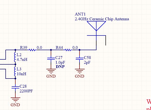
I'd like to tune the pi network based on your white paper nWP-017 and I think I have an understanding of how to do so.

My question is, once I tune the pi filter will C26 throw everything out of balance? What is C26 used for?

Any additional advice or suggestions would be greatly appreciated!

We're at an EMC testing facility and we have access to a network analyzer. We measured the impedance of the antenna and it's feed line and we're at 48 ohms for the real part and we're at -10 for the imaginary part. It seems that the antenna is pretty well matched to 50 ohms as I would expect.

Thanks, Danny

  • We ended up passing EMI testing with this circuit:

    image description

    What makes me nervous is that we removed C26 with a zero ohm. Our performance was 10dB higher than the previous circuit and we passed all harmonics.

    Is there something that I should be concerned about. We can reliably transmit and receive data in this configuration and we are passing EMC testing. I guess when it works, it works but I can't help but think we should be doing something different.

  • To a certain extend we don't have any issues with customers doing tuning like this and following the "if it works and passes, it works and passes"-philosophy.

    To give you some better understand of the components. There's no pi-filter for the antenna in the schematic you have attached originally. All the components from C28 to C58 are there to handle the output of the radio and make sure the output is filtered and converted into a 50 Ohm single ended output. So at C58/L1 is where you have the 50 Ohm point. So the components you have changed is not intended to be used for tuning the antenna, but you can tune what is delivered to the antenna. If I saw this schematic without you telling me that you have passed I would never have recommended doing what you have done, as I would expect you to run into issues with other harmonics or spurious due to the 0 Ohm resistors you have replaced some of the components with. There's nothing wrong with the operation of the radio, it would just be a regulatory issue, but since you have passed everything would be ok from Nordics point of view too.

    Just to be on the safe side here, what you have done works for your application. We still recommend customers to follow Nordics reference layout and schematic closely.

  • To pass FCC testing with the original design, what should we have tweaked? Or would that have depended on the measure impedance looking back at the radio? I looked for a guide to tweak the circuit from nordic semiconductor but didn't see or find anything to this exact circuit. The closest I could find was the white paper mentined above.

Related