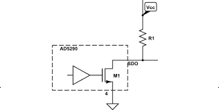
then when you write 0 to the pin, it will drive it to low signal with drive strength of 0.5mA max (standard drive strength). If you write 1 to the pin, it will be disconnected and the external pullup resistor will drive the pin to high signal.
then the pin will be driven to low signal with max 5mA current (high drive strength) when you write 0 to it. When you write 1 it will be disconnected.
Update 25.11.2014
You can use this example directly to test this, just replace the LED configuration line with the configuration code listed above, then you should be able to set pin p0.08 pin by pressing button 0 and clear pin p0.08 with pressing button 1. Remember to change the configuration of the example if necessary so that it fits to your development/evaluation kit, see this thread
Thanks.
However, the output voltage is only about 2.0v when write 1 to the pin, no matter the pin is pulled up to 3.3v or 5.0v. How to get 3.3v output? Thanks again
Its my mistake. The pin is connected to LED, some voltage go to LED, after changed the pin, I got 3.3v output. Yes, the pin can be written as 1 or 0. However, when I try to read the pin, it is always 0 even the pin is HIGH state, so I change the above code with "GPIO_PIN_CNF_INPUT_Connect << GPIO_PIN_CNF_INPUT_Pos", that I can read 1 or 0. Does this change make sene ? Thanks.