I want to use a GPIO as input pin and output pin at the same time with an external pull-up resistor. Thanks.
I want to use a GPIO as input pin and output pin at the same time with an external pull-up resistor. Thanks.
Hi
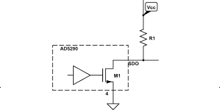
If you intend to control a GPIO pin signal with a connected external pullup resistor with a scenario like in the image bolow

then you can configure the pin in the following manner:
	NRF_GPIO->PIN_CNF[pin_number] = (GPIO_PIN_CNF_SENSE_Disabled << GPIO_PIN_CNF_SENSE_Pos)
                                  | (GPIO_PIN_CNF_DRIVE_S0D1 << GPIO_PIN_CNF_DRIVE_Pos)
				  				  | (GPIO_PIN_CNF_PULL_Disabled << GPIO_PIN_CNF_PULL_Pos)
								  | (GPIO_PIN_CNF_INPUT_Disconnect << GPIO_PIN_CNF_INPUT_Pos)
								  | (GPIO_PIN_CNF_DIR_Output << GPIO_PIN_CNF_DIR_Pos);
then when you write 0 to the pin, it will drive it to low signal with drive strength of 0.5mA max (standard drive strength). If you write 1 to the pin, it will be disconnected and the external pullup resistor will drive the pin to high signal.
If you change the configuration to
(GPIO_PIN_CNF_DRIVE_H0D1 << GPIO_PIN_CNF_DRIVE_Pos)
then the pin will be driven to low signal with max 5mA current (high drive strength) when you write 0 to it. When you write 1 it will be disconnected.
Update 25.11.2014 You can use this example directly to test this, just replace the LED configuration line with the configuration code listed above, then you should be able to set pin p0.08 pin by pressing button 0 and clear pin p0.08 with pressing button 1. Remember to change the configuration of the example if necessary so that it fits to your development/evaluation kit, see this thread
That sounds strange. What resistor value are you using?
That sounds strange. What resistor value are you using?