This post is older than 2 years and might not be relevant anymore
More Info: Consider searching for newer posts

AD5721R problem with SPI latency

Hi,

I am working on a project where I need to create a ~23 kHz square wave signal with a 12-bit DAC (AD5721). The communication works via SPI.

I got it working alright by using the spi driver and the timer driver. The problem is, I can’t reach the desired 23 KHz, but only around 20 KHz.

The program works approximately like this:

  1. Initializing SPI: frequency 8 MHz, SPI Mode 1
  2. Configure DAC
  3. Configure and initialize timer: frequency 8 MHz, Timer counter bit width 32 bit, Interrupt priority 7.
  4. Setting the timer channel in extended compare mode
  5. Call timer handle according to the entered microseconds

Below is the code of the timer handle to switch the output voltage of the DAC. 

bool 		sign = true; //used to switch positiv and negativ output voltage

void dac_timer_handler(nrf_timer_event_t event_type, void* p_context)
{
		if (sign == true){				
			ad5721r_write(CMD_WRITE_UPDATE_DAC_REG, voltagePos);
			sign = false;
		}
		else{	
			ad5721r_write(CMD_WRITE_UPDATE_DAC_REG, voltageNeg);
			sign = true;
		}
}

Here is a snipped of an oscilloscope reading. The timer handle is called every 25 us to toggle between +4V and -4V (square wave signal is 20 KHz). The yellow line is the AD5721 output voltage. The green line is the clock (24 bit, 3us), and the violet line is the SS (SYNC).

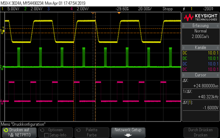
According to the data sheet on page 22 the communication works as it is supposed to:

“The write sequence begins after bringing the SYNC line low, and maintaining this line low until the complete data-word is loaded from the SDI pin. Data is loaded in at the SCLK falling edge transition (see Figure 2). When SYNC is brought high again, the serial data-word is decoded according to the instructions”

Problem: As soon as I decrease the timer tick events below 25 us (here 22 us for a period of 22.73 kHz) I get a square wave signal with an incorrect duty cycle. This can be seen in the oscilloscope image below.

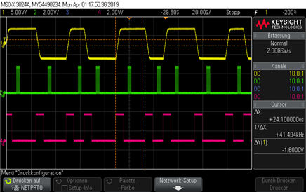
Why isn’t the SYNC brought up to high again directly after the clock and data transfer has ended? Is this a similar problem like this Q&A: https://devzone.nordicsemi.com/f/nordic-q-a/9636/spi-clock-bug. ? 

I’m new to working with Nordic Semi products and still a student. I hope this is not an unnecessary Q&A post.

Thanks a lot in advance for the help.

  • I think the best option is to get yourself an nRF52840-DK instead, this chip have a new SPIM3 module with hardware SYNC (called CSN here) pin and faster clock speed:
    http://infocenter.nordicsemi.com/topic/com.nordic.infocenter.nrf52840.ps/spim.html?cp=2_0_0_5_24 

    If you want to continue investigate a bit the nRF52832 I would likely have tried to look at your interrupt priorities, and for instance toggle a specific pin while timer handler is executing and a different pin when spi handler is running, to check the order of the interrupts or the duration differs also here.

    Make sure to check if the spi driver is using EasyDMA by looking at the sdk_config.h file, e.g.:

    #ifndef SPI0_USE_EASY_DMA
    #define SPI0_USE_EASY_DMA 1
    #endif

    Is the BLE softdevice enabled in your application? and/or other interrupts?

  • Thanks for the quick reply.

    I checked, the spi driver is using EasyDMA. The application so far is pretty bare bone, no BLE softdevice or other interrupts are enabled. But I plan on using Bluetooth in the future.

    The timer handler works fine to toggle a specific pin. Once the SPI handler is running the pin toggle also differs in duration. I’m starting to wonder if the DAC is limiting the frequency output.

    I won’t be able to use the nrf58240 for my project. But good to know for future applications.

  • I resolved the issue by using the spi master driver instance in blocking mode.

    nrf_drv_spi_init(&spi, &spi_config, NULL,NULL);

    And by commenting out the while loop with WFE() in the write function of the DAC.

    void ad5721r_write( uint8_t reg_addr_cmd, uint16_t reg_data)
    {
    	uint8_t data[3];
    	ret_code_t ret;
    
    	data[0] = reg_addr_cmd; 
    	data[1] = (reg_data & 0xFF00) >> 8; 
    	data[2] = (reg_data & 0x00FF) >> 0; 
    
        memset(m_rx_buf, 0, m_length);
    	spi_xfer_done = 0;
    	nrf_drv_spi_transfer(&spi, data, 3, m_rx_buf, 0);
    //	while (!spi_xfer_done)
    //		{
    //			__WFE();
    //		}
    }
    

    I guess this will make it more dangerous to call it too often without checking the status of the transfer? Could this cause bigger issues when using BLE softdevice or other interrupts?

    So far I had no problem running the DAC at 24 KHz and higher.

  • Hi,

    I suspect this works "better" because you don't have any interrupt delays. If you are using the driver in blocking mode (e.g. no callback handler registered when init spi driver), then this should be a safe usage.

    Best regards,
    Kenneth

Related