This post is older than 2 years and might not be relevant anymore
More Info: Consider searching for newer posts

nRF9160 asset tracker configure UART

Hi

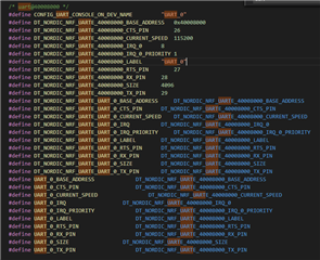
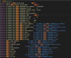
I downloaded and successfully build and ran the asset tracker sample on the nRF9160 DK using segger embedded studio. In a first step I want to reroute the debug UART output to the pins P0.17 and P0.18. Therefore I checked this post and introduced the following nrf9160_pca10090.overlay file.

&uart0 {
current-speed = <115200>;
status = "ok";
tx-pin = <18>;
rx-pin = <17>;
rts-pin = <19>;
cts-pin = <21>;
};

If I clean, build&run the sample again, the debug UART does not change. On pin 18 there is no activity and the debug UART still runs over the interface MCU (checked with PuTTY). I checked that the DTC_OVERLAY_FILE variable is set. What am I missing?

Second, I wanted to introduce a second UART / Serial in the project. What are the required steps to do there. I know it's a very basic question but since there is no tutorial for the Connect SDK yet on how to configure and set up a SES project yes as already pointed out in this post.

I'm running SES 4.14 on Win 8.1 and completed your nRF Connect SDK Getting Started Guide.

Thx for your help! 

  • Hello Marc,

    The configure the UARTx pins, you have to configure the board controller. Please see this thread, which has a good explanation on how to configure the UART.

    Kind regards,
    Øyvind 

  • Hi Øyvind

    Thanks for your answer. I tested your solution and it works. BUT, it's not what I wanted. The solution you provided just configures the analog switch. What I wanted is to change the UART pins on the nRF9160 using software configuration. According to the board controller, pins 17 and 18 should already be routed by default to the Arduino interface. So what do I have to do to configure the UART in software to pins 17 and 18?

    BR, Marc

  • Hello Marc, 

    The overlay file should override the default pins. Where have you placed the overlay file?

    Did you include the UART settings in prj.conf:

    CONFIG_UART_0_NRF_UARTE=y
    CONFIG_UART_0=y
    CONFIG_AT_HOST_UART=0

    These settings need to be added for UART1 as well.

    Can you verify that the pins are configured in the following file:

     samples\nrf9160\asset_tracker\build\zephyr\include\generated\generated_dts_board.h

    You should be able to see what pins have been configured for UART0. 
    My file before overlay:
    generated_dts_board.h before overlay

    And after overlay:

    generated_dts_board.h after overlay

    Hope this helps. Let me know if anything is unclear. 

  • Hi Øyvind

    I did what you told and now I can observe in the generated_dts_board.h the pin numbers change according to the setting in the .overlay file. I also added the lines in the prj.conf file. However, when I build and flash the application, the debug UART is still routed to the Interface MCU.. Do I miss something else in the config process? Does your example run on a DK?

    I checked with the LTE logging from this post if the settings in prj.conf have any effect at all. => yes, this works.

    I'm now using the cmake and ninja cmd line commands to build because with the SES I'm not sure if it always properly porcesses changes in prj.conf and .overlay..

    These settings need to be added for UART1 as well.

    What do you mean with this and why is it necessary?

  • Hi Marc,

    Marc said:
    What do you mean with this and why is it necessary?

    My quote didn't follow the answer, but it was in conjunction to "Second, I wanted to introduce a second UART / Serial in the project".

    Please have a look at this post, this post and this post which discusses the same setup as you. You may have to add the overlay file to secure boot as well. I have not had the time to check if it is running as it should on my side, only verified that the pins are set and that the TX pin is high and RX is floating.


Related