
Hi,
could you please tell where can I find a table showing all the NVIC interrupt vectors?
I searched in the nRF52840 datasheet but I did not find something relevant
Thank you
Hi,
could you please tell where can I find a table showing all the NVIC interrupt vectors?
I searched in the nRF52840 datasheet but I did not find something relevant
Thank you

To give you the short answer first: download the nRF52 SDK and look at the file modules/nrfx/mdk/nrf52840.h. It defines an enum called IRQn_Type which shows you all the vector numbers.
Note that by ARM design conventions, the first 16 slots in the vector table are reserved for CPU-specific things. The vector table is at address 0x0 in the flash. The first two 32-bit words there define the initial stack pointer and reset vector, followed by 14 other CPU-specific vectors. The IRQ numbers for vendor-defined peripheral devices therefore start at the 16th entry in the table and go up from there.
So for a given IRQ number, you can calculate the vector table slot address as follows:
slotaddr = (IRQ number * 4) + (16 * 4)
Where 4 is the size of a vector entry (4 bytes) and 16 is the number of slots reserved for the ARM core stuff described above.
To give you a bit of a longer answer, the nRF52840 product specification does actually tell you the vector offsets, but in a left-handed sort of way. (I refer to this as the Minimum Information Game.)
Look at the Peripherals section in the manual. Choose a given peripheral, for example the I2S controller (section 6.11). Now look at the Registers section (6.11.10). The first thing it tells you is the base address of the I2S register bank, which is 0x40025000.
It turns out that the register bank offset for a peripheral is directly associated with the peripheral's NVIC interrupt. In this case, it's the value 0x25. This is 37 in decimal, and if you look at the IRQn_Type table, you'll see that I2S_IRQn is indeed 37.
As a shortcut, you can also look at the Instantiation table in section 4.2.4. The "ID" column in the table also happens to be the same as the IRQ number.
Note that not every ARM SoC vendor uses the same convention.
Unfortunately I don't think the manual comes right out and says this in the same words that I just did. Arguably it should.
-Bill
Thank you for your reply. Very Helpful! Thank you.
Could you please answer me one more question on IRQs that confuses me?
In the pin_change_int example, of the peripherals folder,
when an input pin state change occurs , the event is serviced with the in_pin_handler() routine
where the LED is toggled.
Where is the interrupt get serviced in the code? There is no interrupt_handler() routine.
So if I get it right, the handler function serves the IRQ of the input pin if the IRQ is enabled or, in case the interrupt is disabled, the same handler routine performs the actions (toggle led) when the event for the input pin is triggered.
I am a little confused
Does the nRF52840 follow the same logic? Because from the pin_change_int example, I understand that both event and interrupt are serviced from the event handler routine...There is no service routine specifically for the external interrupt
Thank you for your time and help
Where is the interrupt get serviced in the code? There is no interrupt_handler() routine.
It's in nrfx_gpiote_irq_handler(). From the vector table, you have the GPIOTE_IRQHandler, and in nrfx_irqs_nrf52840.h, we have that
#define nrfx_gpiote_irq_handler GPIOTE_IRQHandler
and nrfx_gpiote_irq_handler() can be found in nrfx driver folder in nrfx_gpiote.c. See this link.
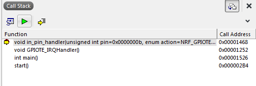
The registred handler( in_pin_handler() in this case) is called at line 707 in the interrupt handler driver, see this link.
Placing a breakpoint in in_pin_handler(), the call-stack looks like this in SES:
Originally you mentioned the AVR processors and how they handled interrupts, but it looks like you edited that part out. There is a similarity in that both the Atmel AVR and ARM processors use the vectored interrupt model. The AVR model is a bit simpler though in that it doesn't have a dedicated interrupt controller block like the NVIC.
The ARM Cortex-M vector table starts at address 0x0 which is in the flash. Every 4 bytes contains the address of the interrupt handler for that vector. When the CPU gets an interrupt, it will branch to the address specified there.
Populating the slots at compile time is done with a little bit of linker magic. If you look at, say, modules/nrfx/mdk/gcc_startup_nrf52840.S, there's a table called __isr_vector which defines the vector table, and it has various slots filled with handler functions, such as GPIOTE_IRQHandler. If you look further down, you'll also see a definition for a simple function called Default_Handler that's just an infinite loop. Right below that are a bunch of aliases with names that match the handler functions specified in the __isr_vector table. You'll see they're prefixed by an "IRQ" macro which defines these alias using the .weak attribute. This is a hint to the linker that these are weak symbols.
What this does is tell the linker: "If someone provides another function with the same name that doesn't have the .weak attribute (i.e. a "strong" symbol), then put that function's address into the vector table, otherwise use the weakly defined one, which is just a do-nothing loop."
So effectively all you need to do to add an interrupt handler is to just create your own function with the right name and then link it in. The linker scripts will tell the linker to put the __isr_vector table at the start of your image and populate it correctly. This is less hassle than having to manually edit the gcc_startup_nrf52840.S file and insert your own ISR every time you want to make a new project (though you could do that if you really wanted to).
I'm pretty sure that if you use avr-gcc/avr-libc to write programs for the AVR chips, it does something very similar.
Nordic then wraps this up in some abstraction macros, which is why instead of using GPIOTE_IRQHandler you use nrfx_gpiote_irq_handler. This makes things a little confusing because if you want to set a breakpoint, you have to tell the debugger to use the actual symbol name GPIOTE_IRQHandler, not the macro name nrfx_gpiote_irq_handler.
Note that what I've just described is the ARM interrupt handling mechanism. You complicated things a little by asking specifically about interrupts for GPIO pin changes. The ARM CPU doesn't really define how that works: lots of vendors use ARM cores (Nordic, NXP, ST Micro, etc...) but they add their own peripheral stack. (By contrast, Atmel is the only one that makes AVR processors and they also design the peripherals.)
In the case of the nRF52840, Nordic has two components: the GPIO component, which lets you configure and control pins, and the GPIOTE component, which is responsible for generating interrupts when the input state of one of the GPIO pins changes.
One thing to be aware of is that while the nRF52840 has 48 pins which can be used as GPIOs, the GPIOTE component has only 8 channels for signalling events. That means that you can only sense interrupts from at most 8 pins at any given time. It works sort of like this:
- You decide you want to be able to sense input changes on pin P0.24
- You configure pin P0.24 as an input, configure pullups, etc... using the GPIO module
- You choose one of the GPIOTE channels, say channel 0
- You program GPIOTE channel 0 to respond to pin P0.24, and select what events you want to respond to (lo to hi, hi to low, both)
Now when the input state of P0.24 changes, the GPIOTE interrupt will fire. The interrupt handler must then check which of the 8 channels signaled a state change (could be more than one if you set up multiple channels), acknowledge the interrupt and act accordingly.
In the Nordic SDK this is abstracted in their driver and library code. What's important to note is that the in_pin_handler() function is not the actual interrupt entry point. The actual entry point is nrfx_gpiote_irq_handler/GPIOTE_IRQHandler, and that function will eventually call back to your in_pin_handler() function.
It's only the GPIO support that's set up like this. For other peripherals, like the UART, SPI controller, I2C controller, etc..., each peripheral has an IRQ directly associated with it. When you use one of the SDK drivers/libraries for a given peripheral, it will provide its own interrupt handler.
-Bill
Wow, one of the best answers ever !!
You should change your nickname from Bill to Guru Bill!
Yes I edited my reply because I wanted to keep things more simple in case I confused you. But in the end, it seems that it was helpful :-)
Now the handler function makes much more sense since nrfx_gpiote_irq_handler is the link I was searching for..
I am new to ARM and that is why all this confusion.
I will study your reply and I will come back with questions.
Again, great explanation! Thank you for your valuable time!
Actually, this post could be a small tutorial about ARM interrupts mechanism.
Best Regards
Lefteris

