This post is older than 2 years and might not be relevant anymore
More Info: Consider searching for newer posts

Problem with external J-Link Interface BMD-350 eval board

Hello,

I am trying to use the BMD-350 evaluation board to program a standalone BMD-350 module on a custom PCB. I have followed the instructions in the documentation to connect the eval board to my custom one, but the internal module on the evaluation board is always the one that is programmed.

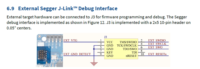
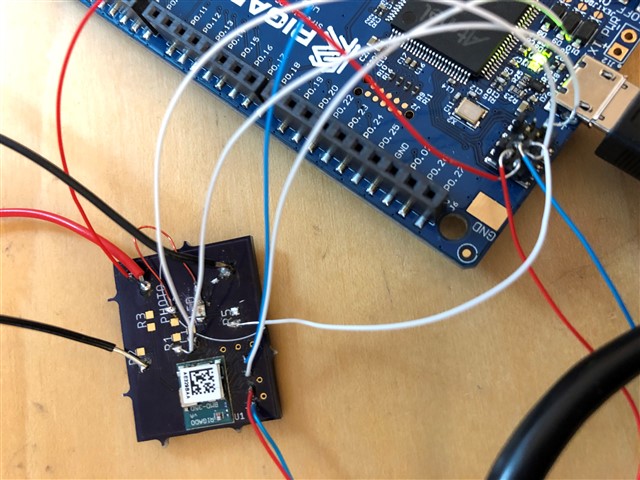
In the images, I have tried to show how the board is connected. With this setup, when I connect the custom PCB to power (without the eval board connected by USB), I see a current of about 170 mA. Then, once I connect the eval board to the computer through USB, this current drops to zero, and the module on the eval board is programmed.

1. If I am not mistaken, in the first image with the instructions, it shows that pins 3 and 5 should be connected to the eval board ground as well as the custom board ground. On my eval board, these pins were not connected to the eval board ground. I connected them to both the eval board ground and the custom ground, but this had no effect on the connection. Am I doing something wrong here?

2. As shown in the second image, the wires I have used for the connections are very thin. While I have confirmed an electrical connection between the pins, is it possible that the connection with these wires are not solid enough for the link?

3. Currently on the custom PCB, the BMD-350 is only connected to power and ground. Is this sufficient to run the module, or do I need anything more for it to function?
Thank you in advance for your help

  • Hi Aritro

    1. This should not be a problem, as long as those pins are grounded it should work.

    2. As long as they are connected correctly and the current goes through, they should work. If you are in doubt, you could always test with thicker wires.

    3. In order to program the chip, you have to connect EXT_SWDIO and EXT_SWCLK to SWDIO and SWDCLK on the target BMD. But to run it once programmed, VDD and GND are sufficient to run the chip.

    Have you been able to confirm that the chip on the custom board is turned on? I would like to take a look at your schematics, to see that everything is connected properly.

    Best regards,

    Simon

  • Hello Simon,

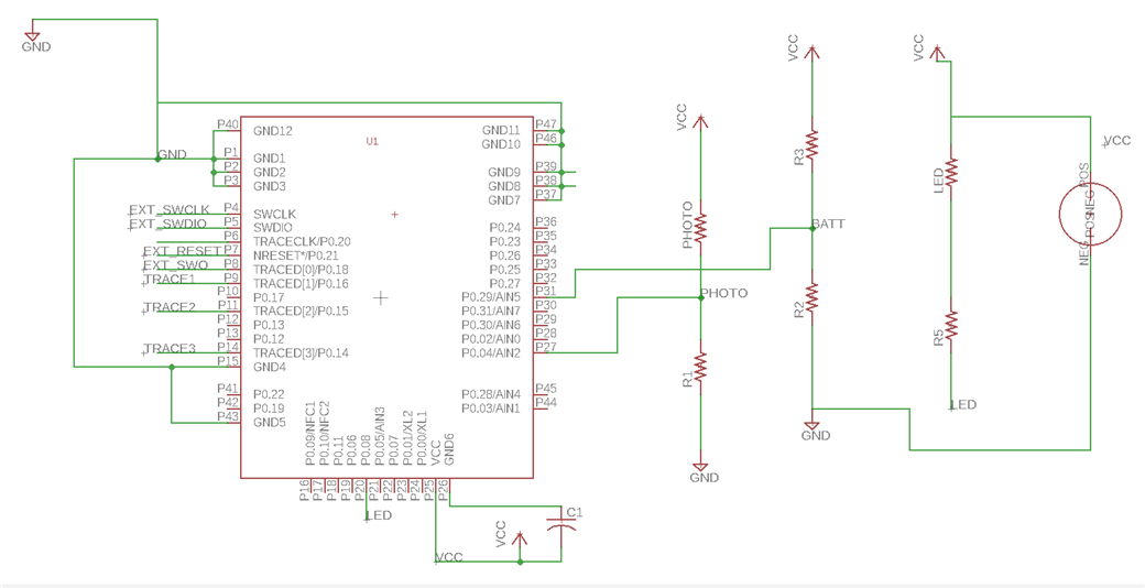
    Thank you for your prompt response. I am still stumped about why this is happening as it looks to me like I have connected everything correctly. My only confirmation that the chip on my board is turned on is that when my board is connected to a 3.2V power source, about 20 mA of current is delivered. However this disappears after I proceed to connect the eval board to my computer. Please find my schematic below. Any help is greatly appreciated. 

    Thanks,

    Aritro

  • Hi Aritro

    Have you added the necessary clocks to the BMD-350 module? It is stated in its data sheet (chapter 9.7 Clocks) that the BMD-350 requires two clocks, a high frequency and a low frequency clock that should be connected to XL1/XL2 and XC1/2. Please refer to the data sheet and our reference designs to see what clocks and how they should be placed.

    Best regards,

    Simon

  • Hi Simon,

    Are those clocks necessary for the programming specifically? I believe that the datasheet says that both of these clocks can be provided internally. Additionally, when I power my module without connecting to the bmd-350 eval board, I do see a RigCom advertisement, which indicates to me that the module is working. I still can't figure out why I am unable to program the external module with the eval board.

    Thanks,

    Aritro

  • Hi

    The high frequency clock (32MHz connected to XC1 and XC2) is necessary to make the nRF chip run properly in the first place. The low freq. clock is usually optional, but since the data sheet states that it is required you most likely need that as well. In conclusion, yes, you do need these clocks.

    Best regards,

    Simon

Related