Hello,
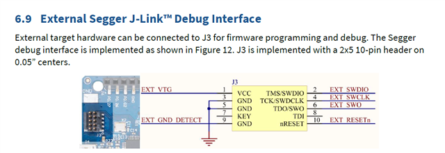
I am trying to use the BMD-350 evaluation board to program a standalone BMD-350 module on a custom PCB. I have followed the instructions in the documentation to connect the eval board to my custom one, but the internal module on the evaluation board is always the one that is programmed.
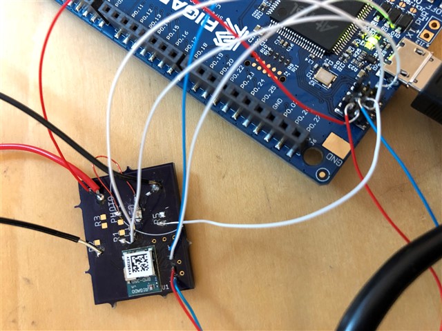
In the images, I have tried to show how the board is connected. With this setup, when I connect the custom PCB to power (without the eval board connected by USB), I see a current of about 170 mA. Then, once I connect the eval board to the computer through USB, this current drops to zero, and the module on the eval board is programmed.
1. If I am not mistaken, in the first image with the instructions, it shows that pins 3 and 5 should be connected to the eval board ground as well as the custom board ground. On my eval board, these pins were not connected to the eval board ground. I connected them to both the eval board ground and the custom ground, but this had no effect on the connection. Am I doing something wrong here?
2. As shown in the second image, the wires I have used for the connections are very thin. While I have confirmed an electrical connection between the pins, is it possible that the connection with these wires are not solid enough for the link?
3. Currently on the custom PCB, the BMD-350 is only connected to power and ground. Is this sufficient to run the module, or do I need anything more for it to function?


Thank you in advance for your help

