This post is older than 2 years and might not be relevant anymore
More Info: Consider searching for newer posts

PCB antenna impedance

Hi All

I have attached a drafting . should I need to control impedance like that when PCB is manufacturing . image description

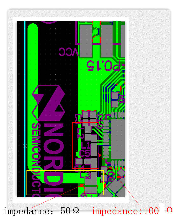
I look forward to receiving your prompt reply.

Parents
  • No, the impedance will be 50 Ohm at the output of the matching network for the radio. I believe that would be at the intersection of L3 and C6. Then C5 is used for tuning the antenna input impedance seen from L3 and C6 into 50 Ohm. You check this during development by confirming that the output power is good or the range is fine. You shouldn't need to check this in production.

    Also, the impedance inside the red square won't be 100 Ohm, it will be unknown at the different locations. The only place you know you'll have a known impedance is the 50 Ohm place between L3, C6 and C5.

  • Hi Asbjørn

    I have some confusion . For the red square ,is it nacessary that the Q value of L1、L2 and L3 should to be considered ? Is it right that if we do not match the red square ,the outpower loss will increase .

Reply Children
No Data
Related