This post is older than 2 years and might not be relevant anymore
More Info: Consider searching for newer posts

AT24C512 + BMI160 + NRF52

Hi,

I am using nRF52832 soc to develop my project. with nRF5_SDK_15.3 . SES file

I need to connect both BMI160 accelerometer sensor and AT24C512 EEPROM ic in TWI.

how to use TWI with this. guide me to use both at a time.

BMI160 separately i can read the data.

but i can't read while connect to AT24C512

Parents
  • Hi, 

    I recommend reading the TWIM chapter and the TWIS chapter in the product specification for nRF52832.

    The master device (TWIM) is in your case the nRF58832, while sensor and EEPROM are slaves. 

    If your nRF52832 will work as a slave (TWIS), then you need another microcontroller functioning as a master.

    You will find a suitable example to communicate with two devices in the TWI Transaction Manager Example which I linked to yesterday.

    Kind regards,
    Øyvind

  • Hi, Can you please tell me what is the difference of  TWI0 and TWI1

    #ifndef TWI0_ENABLED
    #define TWI0_ENABLED 1
    #endif
    // <q> TWI0_USE_EASY_DMA  - Use EasyDMA (if present)
     
    
    #ifndef TWI0_USE_EASY_DMA
    #define TWI0_USE_EASY_DMA 1
    #endif
    
    // </e>
    
    // <e> TWI1_ENABLED - Enable TWI1 instance
    //==========================================================
    #ifndef TWI1_ENABLED
    #define TWI1_ENABLED 0
    #endif
    // <q> TWI1_USE_EASY_DMA  - Use EasyDMA (if present)
     
    
    #ifndef TWI1_USE_EASY_DMA
    #define TWI1_USE_EASY_DMA 0
    #endif

    shall i enable both twi instance.

    what is

    TWI0_USE_EASY_DMA 1  - use case?

    #define TWI1_USE_EASY_DMA 0 - use case?

    if i enable both twi instance

    means

    the EASY_DMA of TWI1 also be '1' or '0'

  • Can you please tell me what is the difference of  TWI0 and TWI1

    Again, look at the Product Specification!

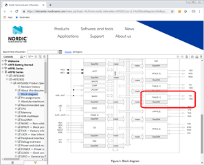
    The Block Diagram clearly shows you that there are two TWIM modules - called "TWIM0" and "TWIM1":

    Yes, you could use both modules - with one slave on each.

    But the whole point of I2C as a bus is that each one can support multiple peripherals - as showed:


  • hi,

    please verify the code:

    
    #include <stdio.h>
    #include "boards.h"
    #include "app_util_platform.h"
    #include "app_error.h"
    #include "nrf_drv_twi.h"
    #include "nrf_delay.h"
    #include "bmi160.h"
    
    #include "nrf_log.h"
    #include "nrf_log_ctrl.h"
    #include "nrf_log_default_backends.h"
    
    
    #define G_TO_LSB (16384.0f)
    
    #define DPS_TO_LSB (131.072f)
    #define I2C_24C128_SLAVE_ADDR        (0x57)
    #define BMI160_I2C_ADDR1                      UINT8_C(0x68)
    
    #define ARDUINO1_I2C_SCL_PIN 30
    #define ARDUINO1_I2C_SDA_PIN 31
    /* TWI instance ID. */
    #define TWI0_INSTANCE_ID     0
    #define TWI1_INSTANCE_ID     1
    
    struct bmi160_dev sensor;
    struct bmi160_sensor_data accel;
    struct bmi160_sensor_data gyro;
    struct bmi160_int_settg int_config;
    
    int8_t rslt = BMI160_OK;
    /* Indicates if operation on TWI has ended. */
    static volatile bool m_xfer_done = false;
    
    /* TWI instance. */
    static const nrf_drv_twi_t m_twi_mma_EEP = NRF_DRV_TWI_INSTANCE(TWI0_INSTANCE_ID);
    static const nrf_drv_twi_t m_twi = NRF_DRV_TWI_INSTANCE(TWI1_INSTANCE_ID);
    
    void eep_WriteByte(uint16_t eep_address, unsigned char val);
    unsigned char eep_readByte(uint16_t eep_address);
    ret_code_t err_codecpy;
    float accelX;


    void twi_init (void)
    {
        ret_code_t err_code;
    
        const nrf_drv_twi_config_t twi_mma_EEP_config  = {
           .scl                = ARDUINO1_I2C_SCL_PIN,
           .sda                = ARDUINO1_I2C_SDA_PIN,
           .frequency          = NRF_DRV_TWI_FREQ_100K,
           .interrupt_priority = APP_IRQ_PRIORITY_HIGH,
           
        };
        const nrf_drv_twi_config_t twi_config = {
           .scl                = ARDUINO_SCL_PIN,
           .sda                = ARDUINO_SDA_PIN,
           .frequency          = NRF_DRV_TWI_FREQ_100K,
           .interrupt_priority = APP_IRQ_PRIORITY_HIGH,
          // .clear_bus_init     = false
        };
    
        err_code = nrf_drv_twi_init(&m_twi_mma_EEP, &twi_mma_EEP_config, NULL, NULL); //twi_handler
         APP_ERROR_CHECK(err_code);
        if (NRF_SUCCESS == err_code)
    	{
    		nrf_drv_twi_enable(&m_twi_mma_EEP);
    		NRF_LOG_INFO("TWI0 init success...");	
    	}
        err_code = nrf_drv_twi_init(&m_twi, &twi_config, NULL, NULL);
    
           APP_ERROR_CHECK(err_code);
        if (NRF_SUCCESS == err_code)
    	{
    		nrf_drv_twi_enable(&m_twi);
    		NRF_LOG_INFO("TWI init success...");	
    	}
    		
       err_codecpy=err_code;
    		nrf_delay_ms(5);
    }
    
    unsigned char eep_readByte(uint16_t eep_address){
    
        unsigned char eep_by_address[2];
    unsigned char reg=0;
        eep_by_address[1]   = eep_address;
        eep_by_address[0] = (unsigned char)(eep_address << 8);
        // setting the start address
        nrf_drv_twi_tx(&m_twi_mma_EEP, I2C_24C128_SLAVE_ADDR, eep_by_address, 2, true);
        // read a byte
        nrf_delay_ms(5);
    
        nrf_drv_twi_rx(&m_twi_mma_EEP, I2C_24C128_SLAVE_ADDR, &reg,1);
    
        nrf_delay_ms(5);
    	return reg;
    }
    void eep_WriteByte(uint16_t eep_address, unsigned char val){
    
        unsigned char eep_by_address[3];
        eep_by_address[2] = val;
        eep_by_address[1] = eep_address;
        eep_by_address[0] = (unsigned char)(eep_address << 8);
    
        err_codecpy = nrf_drv_twi_tx(&m_twi_mma_EEP, I2C_24C128_SLAVE_ADDR, eep_by_address, 3, false);
        nrf_delay_ms(5);
        if(err_codecpy == 0)
        {
          NRF_LOG_INFO("\r\nWritten Sucess");
        NRF_LOG_FLUSH();
        }
    
    }
    
    int8_t Acc_i2c_Write(uint8_t dev_id, uint8_t reg_addr, uint8_t *reg_data, uint16_t len)
    {
    
        //  NRF_LOG_INFO("WRITE: dev_id: %x reg_addr: %x reg_data: %x len: %i\n", dev_id, reg_addr, *reg_data, len);
    	int8_t rslt = 0;
    	uint8_t data[len + 1];
    	data[0] = reg_addr;
    	for (uint16_t i = 0; i < len; i++) {
    		data[i + 1] = reg_data[i];
    	}
    	
    	rslt = nrf_drv_twi_tx(&m_twi, dev_id, data, len + 1, false);
    	APP_ERROR_CHECK(rslt);
            return rslt;
      
    }
    
    
    int8_t Acc_i2c_Read(uint8_t dev_id, uint8_t reg_addr, uint8_t *reg_data, uint16_t len)
    {
    	int8_t rslt = 0;
       //     NRF_LOG_INFO("READ: dev_id: %x reg_addr: %x len: %i\n", dev_id, reg_addr, len);
    	rslt = nrf_drv_twi_tx(&m_twi, dev_id, &reg_addr, 1, false);
            APP_ERROR_CHECK(rslt);
    
    	if (rslt == 0)
    	{
    		rslt = nrf_drv_twi_rx(&m_twi, dev_id, reg_data, len);
    	}
        //    NRF_LOG_INFO("READ: %x",*reg_data);
    	return rslt;
    }
    
    void Acc_delay_ms(uint32_t period)
    { 
    	
    /*if (period==NULL){
    period = 1;
    }// delay time*/
    	
      nrf_delay_ms( period ) ;
    }
    
    void BMI_init (void)
    {
        sensor.id = BMI160_I2C_ADDR;         //0x69
        sensor.interface = BMI160_I2C_INTF;  //0x00
        sensor.read = &Acc_i2c_Read;
        sensor.write = &Acc_i2c_Write;
        sensor.delay_ms = &Acc_delay_ms;
    
        rslt = bmi160_init(&sensor);
        APP_ERROR_CHECK(rslt);
    
        if(rslt == BMI160_OK){
        NRF_LOG_INFO("BMI160 Initialized...");
        } else {
        NRF_LOG_INFO("BMI160 not Initialized...");
        }NRF_LOG_FLUSH();
    
        sensor.accel_cfg.odr = BMI160_ACCEL_ODR_1600HZ;
        sensor.accel_cfg.range = BMI160_ACCEL_RANGE_2G;
        sensor.accel_cfg.bw = BMI160_ACCEL_BW_NORMAL_AVG4;
        sensor.accel_cfg.power = BMI160_ACCEL_NORMAL_MODE;
    
        sensor.gyro_cfg.odr = BMI160_GYRO_ODR_3200HZ;
        sensor.gyro_cfg.range = BMI160_GYRO_RANGE_2000_DPS;
        sensor.gyro_cfg.bw = BMI160_GYRO_BW_NORMAL_MODE;
        sensor.gyro_cfg.power = BMI160_GYRO_NORMAL_MODE;
    
        rslt = bmi160_set_sens_conf(&sensor);
        APP_ERROR_CHECK(rslt);
    
         if(rslt == BMI160_OK){
        NRF_LOG_INFO("sensor Configured...");
        } else {
        NRF_LOG_INFO("sensor not Configured...");
        }NRF_LOG_FLUSH();
    }
    
    static void read_sensor_data()
    {
          m_xfer_done = false;
          bmi160_get_sensor_data((BMI160_ACCEL_SEL | BMI160_GYRO_SEL | BMI160_TIME_SEL), &accel, &gyro, &sensor);
          /*NRF_LOG_INFO("DataX:%d", accel.x);
          NRF_LOG_INFO("DataY:%d", accel.y);
          NRF_LOG_INFO("DataZ:%d", accel.z);
          NRF_LOG_INFO("GyroX:%d", gyro.x);
          NRF_LOG_INFO("GyroY:%d", gyro.y);
          NRF_LOG_INFO("GyroZ:%d", gyro.z);*/
    
          /* need the calculation to study  */
          accelX = ((((float)accel.x) / G_TO_LSB) * 9.80655); // in m/s^2
          float gyrX = ((((float)gyro.x) / DPS_TO_LSB) * 0.0174532925); // in rad/sec
          NRF_LOG_INFO("DataX in m/s^2   : " NRF_LOG_FLOAT_MARKER, 
          NRF_LOG_FLOAT( accelX));
          NRF_LOG_INFO("DataY in rad/sec : " NRF_LOG_FLOAT_MARKER, 
          NRF_LOG_FLOAT(gyrX));
          NRF_LOG_FLUSH();
    }
    
    
    /**
     * @brief Function for main application entry.
     */
    int main(void)
    {
        APP_ERROR_CHECK(NRF_LOG_INIT(NULL));
        NRF_LOG_DEFAULT_BACKENDS_INIT();
        NRF_LOG_INFO("\r\nTWI sensor example started.");
        NRF_LOG_FLUSH();
        twi_init();
        NRF_LOG_FLUSH();
    
    	unsigned char  reg1 = 0;
            Acc_delay_ms(50);
    
        BMI_init();
        Acc_delay_ms(100);
        uint8_t reg_addr = BMI160_CHIP_ID_ADDR;
        uint8_t data;
        uint16_t len = 1;
        Acc_delay_ms(1000);
        rslt = bmi160_get_regs(reg_addr, &data, len, &sensor);
        NRF_LOG_INFO("Data:%x", data);
        eep_WriteByte(0x0000,data);
    
        while(true)
        {
            nrf_delay_ms(1000);
    		//	    eep_WriteByte(0x0000,'w');
    	 nrf_delay_ms(5);
    	//eep_WriteByte(0x0001,'B');
    	 nrf_delay_ms(5);
    	   reg1=eep_readByte(0x0000);
    	if(reg1!=0){
    		NRF_LOG_INFO("\r\n Read value 00 : %x",reg1);
                    NRF_LOG_FLUSH();
                    nrf_delay_ms(5);
    	}
    
    	else if(reg1==0){
    	 nrf_delay_ms(5);
    	}
            reg1=eep_readByte(0x00051);
    	if(reg1!=0){
    		NRF_LOG_INFO("\r\n Read value 51 : %c",reg1);
                    NRF_LOG_FLUSH();
                    nrf_delay_ms(5);
    	}
    	else if(reg1==0){
    	 nrf_delay_ms(5);
    	}
            read_sensor_data();
            eep_WriteByte(0x00051,accelX);
            reg1=eep_readByte(0x00051);
    	if(reg1!=0){
    		NRF_LOG_INFO("\r\n Read value 51 : %d",reg1);
                    NRF_LOG_FLUSH();
                    nrf_delay_ms(5);
    	}
    	else if(reg1==0){
    	 nrf_delay_ms(5);
    	}


        }
    }


    output:

    it works in two different TWI wire pins

    that is

    eeprom  scl in 27

    eeprom sda in 26

    bmi scl in 30

    bmi sda in 31

    .

    if i give same sda and scl pin to eeprom and bmi. it gives fatal error ;

    can you give how to manage this in single TWI wire.

    i have seen TWI mangr

    in that

    i have difficult to interface the eeprom with bmi

    can you give a solution

  • if i give same sda and scl pin to eeprom and bmi. it gives fatal error

    If you're going to use two separate TWI Masters, then they need to be separate - they cannot share the same pins!

    Again, this is clearly stated in the Product Specification:

    "Only one peripheral can be assigned to drive a particular GPIO pin at a time. Failing to do so may result in unpredictable behavior."

  • As the device has EasyDMA present, you want to enable this:

    TWI0_USE_EASY_DMA 1

  • I'm sorry, I am not able to see what is wrong from your code. Can you please debug the code and give me the error message you receive with the fatal error?

    Kind regards,
    Øyvind

Reply Children
  • The error code

    #define ARDUINO_SCL_PIN             27    // SCL signal pin
    #define ARDUINO_SDA_PIN             26    // SDA signal pin
    #define ARDUINO1_I2C_SCL_PIN 30
    #define ARDUINO1_I2C_SDA_PIN 31
    
    void twi_init (void)
    {
        ret_code_t err_code;
    
        const nrf_drv_twi_config_t twi_mma_EEP_config  = {
           .scl                = ARDUINO_SCL_PIN,
           .sda                = ARDUINO_SDA_PIN,
           .frequency          = NRF_DRV_TWI_FREQ_100K,
           .interrupt_priority = APP_IRQ_PRIORITY_HIGH,
           
        };
        const nrf_drv_twi_config_t twi_config = {
           .scl                = ARDUINO_SCL_PIN,
           .sda                = ARDUINO_SDA_PIN,
           .frequency          = NRF_DRV_TWI_FREQ_100K,
           .interrupt_priority = APP_IRQ_PRIORITY_HIGH,
          // .clear_bus_init     = false
        };
    
        err_code = nrf_drv_twi_init(&m_twi_mma_EEP, &twi_mma_EEP_config, NULL, NULL); //twi_handler
         APP_ERROR_CHECK(err_code);
        if (NRF_SUCCESS == err_code)
    	{
    		nrf_drv_twi_enable(&m_twi_mma_EEP);
    		NRF_LOG_INFO("TWI0 init success...");	
    	}
        err_code = nrf_drv_twi_init(&m_twi, &twi_config, NULL, NULL);
    
           APP_ERROR_CHECK(err_code);
        if (NRF_SUCCESS == err_code)
    	{
    		nrf_drv_twi_enable(&m_twi);
    		NRF_LOG_INFO("TWI init success...");	
    	}
    		
       err_codecpy=err_code;
    		nrf_delay_ms(5);
    }

    code changed

    #define ARDUINO_SCL_PIN             27    // SCL signal pin
    #define ARDUINO_SDA_PIN             26    // SDA signal pin
    #define ARDUINO1_I2C_SCL_PIN 30
    #define ARDUINO1_I2C_SDA_PIN 31
    
    void twi_init (void)
    {
        ret_code_t err_code;
    
        const nrf_drv_twi_config_t twi_mma_EEP_config  = {
           .scl                = ARDUINO1_I2C_SCL_PIN,
           .sda                = ARDUINO1_I2C_SDA_PIN,
           .frequency          = NRF_DRV_TWI_FREQ_100K,
           .interrupt_priority = APP_IRQ_PRIORITY_HIGH,
           
        };
        const nrf_drv_twi_config_t twi_config = {
           .scl                = ARDUINO_SCL_PIN,
           .sda                = ARDUINO_SDA_PIN,
           .frequency          = NRF_DRV_TWI_FREQ_100K,
           .interrupt_priority = APP_IRQ_PRIORITY_HIGH,
          // .clear_bus_init     = false
        };
    
        err_code = nrf_drv_twi_init(&m_twi_mma_EEP, &twi_mma_EEP_config, NULL, NULL); //twi_handler
         APP_ERROR_CHECK(err_code);
        if (NRF_SUCCESS == err_code)
    	{
    		nrf_drv_twi_enable(&m_twi_mma_EEP);
    		NRF_LOG_INFO("TWI0 init success...");	
    	}
        err_code = nrf_drv_twi_init(&m_twi, &twi_config, NULL, NULL);
    
           APP_ERROR_CHECK(err_code);
        if (NRF_SUCCESS == err_code)
    	{
    		nrf_drv_twi_enable(&m_twi);
    		NRF_LOG_INFO("TWI init success...");	
    	}
    		
       err_codecpy=err_code;
    		nrf_delay_ms(5);
    }

    when i changed the different scl sda pins separate then it works

    but my case i need to connect both eeprom and sensor in a same pins

  • when i changed the different scl sda pins separate then it works

    That has already been explained to you: you cannot have two different TWI Masters sharing the same pins!

    i need to connect both eeprom and sensor in a same pins

    Then you must use just one TWI Master - as  showed you in the diagram he posted earlier:

  • I'm sorry, but this is just code from your software. I need you to debug your software.

    Please see this page.

    Kind regards,
    Øyvind

  • Thank you,

    i understand what awneil going to tell. but my concern is to make multiple slaves for a one master is getting complexes.

    can yu please explain how this example works.

    https://infocenter.nordicsemi.com/index.jsp?topic=%2Fstruct_sdk%2Fstruct%2Fsdk_nrf5_latest.html&cp=5_0

    can you please how these functions are working:

    NRF_TWI_MNGR_DEF(m_nrf_twi_mngr, MAX_PENDING_TRANSACTIONS, TWI_INSTANCE_ID);
    APP_TIMER_DEF(m_timer);


     err_code = nrf_twi_mngr_init(&m_nrf_twi_mngr, &config);
        APP_ERROR_CHECK(err_code);


         APP_ERROR_CHECK(nrf_twi_mngr_perform(&m_nrf_twi_mngr, NULL, lm75b_init_transfers,
            LM75B_INIT_TRANSFER_COUNT, NULL));
            
        APP_ERROR_CHECK(nrf_twi_mngr_perform(&m_nrf_twi_mngr, NULL, mma7660_init_transfers,
            MMA7660_INIT_TRANSFER_COUNT, NULL));
    

  • Sunil vignesh said:
    but my concern is to make multiple slaves for a one master is getting complexes.

     In your case, you should only need to configure one master. As long as the sensor and EEPROM are connected and powered correctly, you should only need to issue their address and then the command (as per the I2C standard).


    Sunil vignesh said:
    can yu please explain how this example works.

     Not sure what example you mean, as the link points to the start of the SDK documentation.


    Sunil vignesh said:
    can you please how these functions are working:

     These are part of the Common Application Error Handler, more information here and here.

    Kind regards,

    Øyvind

Related