This post is older than 2 years and might not be relevant anymore
More Info: Consider searching for newer posts

nrf52832 meander antenna

Hi there,

I am trying to design a printed meander antenna for the nrf52832. For this purpose I copied the antenna trace from the usb dongle that Nordic Semi produces. However I am still very uncertain about a lot of design parameters. So I was wondering if anybody here has successfully implemented a PCB antenna for the nrf52832, and is willing to share their schematic and layout. Particularly of the transmission line, tuning network and antenna itself. 

Thanks for your help.

Best,

smo

Parents
  • Hi,


    Plenty designs exist with PCB antennas, some of our reference designs as examples:


    None of these probably illustrate the transmission line very well, for this you migth want to take a look at the power profiler kit, it has a longer transmission line.


    What exactly is it you are wondering about? It might be easier to explain it rather than trying to assume what has been done in a different resign.


    Best regards,

    Andreas

  • Well. For one, if I calculate the width of a 50Ohm transmission (eps=4.3, d_pcb=1.6mm) with a coplanar waveguide tool I get a result in the vicinity of 2mm which seems very large. None of the examples seem to have transmission lines that wide. So are those really 50Ohm or what's going on here? 

    Another thing that bothers me are the exact dimensions of the antenna on the USB dongle. Measuring them as well as I could from the CAD files I found that some of the distances decrease slightly with every turn, which seems odd to me. Especially so, because none of the meander antennas out there that I found do that. I would be much more comfortable taking those measurements from a proper technical drawing rather than measuring them from KiCad files that I converted from Altium files.

    Since my range requirements are pretty minimal (~2m) I feel I might be able to get away with minimal tuning effort if I had the design right. Some 3rd party products like the Sparkfun breakout board (https://www.sparkfun.com/products/13990) don't seem to even bother tuning their antenna at all and still achieve basic RF performance. (Btw their transmission line isn't 2mm wide neither.) 

    Best,

    Moritz

Reply
  • Well. For one, if I calculate the width of a 50Ohm transmission (eps=4.3, d_pcb=1.6mm) with a coplanar waveguide tool I get a result in the vicinity of 2mm which seems very large. None of the examples seem to have transmission lines that wide. So are those really 50Ohm or what's going on here? 

    Another thing that bothers me are the exact dimensions of the antenna on the USB dongle. Measuring them as well as I could from the CAD files I found that some of the distances decrease slightly with every turn, which seems odd to me. Especially so, because none of the meander antennas out there that I found do that. I would be much more comfortable taking those measurements from a proper technical drawing rather than measuring them from KiCad files that I converted from Altium files.

    Since my range requirements are pretty minimal (~2m) I feel I might be able to get away with minimal tuning effort if I had the design right. Some 3rd party products like the Sparkfun breakout board (https://www.sparkfun.com/products/13990) don't seem to even bother tuning their antenna at all and still achieve basic RF performance. (Btw their transmission line isn't 2mm wide neither.) 

    Best,

    Moritz

Children
  • Hi,


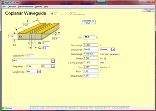
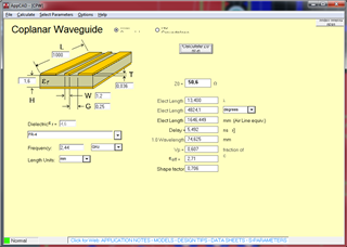
    2mm width might seem quite wide, yes, but the impedance also depends on the gap between the line and the ground pour in the same layer. At ~0.5mm gap you should see about 50 ohms:


    The dimensions we use in our development kit as a comparison:


    The nRF52840 dongle is based on the dimensions in this attachment:

    nRF24LU1 USB Dongle Antenna dimensions.pdf

    You seem to be correct that the nRF52840 dongle is slightly shorter in the last 'bend', not exactly sure why this is, but the dongle antenna has been tested, verified and tuned as is.


    The sparkfun board uses an inverted F variant, which in theory is 50 ohm due to the short stub. Commonly this is not the case but they might have been lucky. I also do not know what considerations they have made: they might have consider it good enough to not justify the cost of extra tuning. 2m range should be piece of cake though.


    Best regards,

    Andreas

Related