This post is older than 2 years and might not be relevant anymore
More Info: Consider searching for newer posts

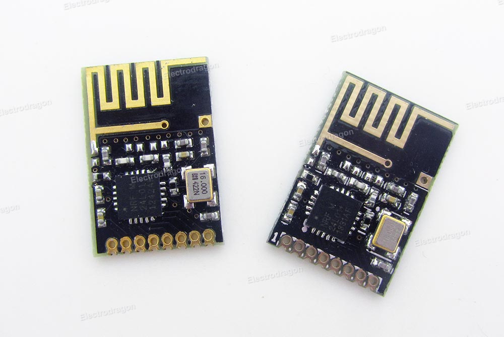
nrf24l01+, pcb mifa antenna design

Hello guys,

I tried to design a pcb antenna for a nrf24l01+, since my company doesnt allow to buy cheap smd breakout board version from china anymore
The pcb stats of the producer:

  • 2-layer FR4 1.55mm (61.023mil)  thickness, εr = 4.6
  • Copper thickness, 35μm (1.378mil)

What I used:

This results into following desgin block:


The antenna area is clear of any signals aswell as ground on top or bottom layer.

Since I have absolutly zero experience with RF antenna design I would like to have some opinions regarding my design.

Thanks so far,

Joe

  • Joe, pretty much everything is wrong on your design.  (sorry)

    On the antenna it is unlikely you can follow the guidelines and come up with something that works.  You need to model it. Standard FR4 while normally 4.6 Er at 10MHz is closer to 4.3 at 2.4GHz. Rarely do the pcb vendors spec it correctly and often just include the 10 or 100MHz value.

    To model it you can use the free version of Sonnet.  It can normally handle a mifa.  In fact I think the demo comes with a mifa for cell band.

    But even easier is to just copy someone elses mifa.  TI publishes one in their BLE docs that is nice.  It shows up on all their dev boards. Nordic uses a similar one on their BLE usb stick.  But not sure if they publish the artwork.

    After that your routing for the RF off the chip is just a disaster.  It will never work.  You routed it like it was DC. Since you don't know RF you should copy the routing from a reference design.  Everything off of the RF needs to be characterized.

    While you are doing that you should spend some time looking over the reference designs so that you get the chip epad grounding right with the correct vias and also get all the DC caps hooked up correctly with the correct grounding. Right now all that stuff on your design is just a train wreck. And, your chip parts are way too big.  They appear to be 0603 or 0805. You need to do the RF with 0402 or 0201 and if you copy someone elses routing you need to use the same size components.  At 2.4GHz there is a big phase difference across the length of a 60 or 80 mil long part so it is much easier to plan and use 20 or 40 mil long parts. I always tell people at 2.4GHz 1mm is almost 10 degrees so 2mm for an 0805 part is 20 degrees which is a lot.  On the smith chart it can easily change a shunt solution to a series solution or a capacitive solution to an inductor solution.

  • Hello Joe, 

    Attached nRF24L01+ Evaluation kit design files, which includes documentation, firmware, hardware, and software. 

    Folder "Documents" contains all available documents related to the nRF24L01+ Evaluation Kit
    Folder "Firmware" contains the source code for the firmware that runs on the MCU in the nRF24L01+ Evaluation kit.
    Folder "Software" contains the setup file for the Windows XP compatible program "nRF24L01+ Evaluation and Configuration"
    Folder "Hardware" contains the gerber files for the RF modules that comes with the nRF24L01+ Evaluation kit


    Please read the comment from , and then use the attached documents as a starting point to learn about RF layout.

    nRF24L01P-EK.zip

    Kind regards,
    Øyvind

  • Hey guys,

    first of all, thank you very much for your advice.
    After reading your posts and checking the files Oyvind has attached to his post I came up with following plan:

    1. Place all components and use the same size shown in the files

    2. Copy the pcb antenna

    3. Check routing

    Since I dont have very much experience with RF, as you already found out, I obviously have some (stupid) questions:

    • My pcb is a little bit thinner than the pcb used in the files. Does this have a big effect on the performance if I just use the same dimensions?
    • What about the line thickness, Antenna length etc.? I there a way to obtain the exact dimensions like width an length? Does it have to be very precise or is it not that important so I can try to measure the lines via grafic tools or something like this? This will result in little differences I guess.
  • JoE1205 said:
    I came up with following plan:

     We recommend that you copy and place the antenna first, as this is the most important part of the RF design. Keep in mind that the reference design is designed for optimal performance.

    For best result, copy the exact antenna layout with the nrf42le1, and antenna components (connected to ANT1 and ANT2). Keep space around the components and GND layer. For the antenna itself, remove any fill around and on the bottom layer.

    Then place other components and route them as wanted. 

    JoE1205 said:
    My pcb is a little bit thinner than the pcb used in the files. Does this have a big effect on the performance if I just use the same dimensions?

     No, this should be fine. Down to 0.8mm will not affect the performance.

    JoE1205 said:
    What about the line thickness, Antenna length etc.? I there a way to obtain the exact dimensions like width an length? Does it have to be very precise or is it not that important so I can try to measure the lines via grafic tools or something like this? This will result in little differences I guess.

     For the antenna and circuit, keep everything exactly the same to be on the safe side. The length of the antenna, seen in the image above, is that length in case you need to tune the antenna. See White Paper - Antenna Tuning v1.0.

    Kind regards,
    Øyvind

  • Some questions regarding the crystal.
    I cant find a crystal with +-60 ppm. Is +-50 also possible?
    The BOM is listing a HC49. Does this include any HC49/xxxx versions, for example HC49/4HSMX?

Related