This post is older than 2 years and might not be relevant anymore
More Info: Consider searching for newer posts

nrf24l01+, pcb mifa antenna design

Hello guys,

I tried to design a pcb antenna for a nrf24l01+, since my company doesnt allow to buy cheap smd breakout board version from china anymore
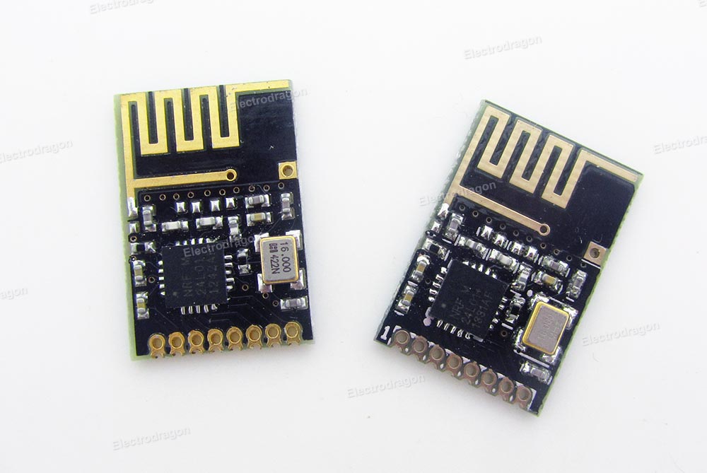
The pcb stats of the producer:

  • 2-layer FR4 1.55mm (61.023mil)  thickness, εr = 4.6
  • Copper thickness, 35μm (1.378mil)

What I used:

This results into following desgin block:


The antenna area is clear of any signals aswell as ground on top or bottom layer.

Since I have absolutly zero experience with RF antenna design I would like to have some opinions regarding my design.

Thanks so far,

Joe

Parents
  • Hey guys, Im back Slight smile

    the current state of me trying to copy the design is the following. I designed it as a design block in EAGLE in order to import it into my project later. Thats why GND-plane is not implemented yet.

    Had to find an other crystal which fits the requirements mentioned by AmbystomaLabs.
    So far the GND-plane is planned for the dotted area, whereas the antenna is planed to be free of GND or any other signals on top and bottom layer.  Anyway Im unhappy with this huge empty space on the left. I guess its okay to reduce the size, but Im unsure about the holes. Is it okay to remove them completely and basicly cut everything whats not needed on the left? By the way: Whats the intention behind placing all the holes? Whats their use? I cant find a clear pattern so for me it looks very random. Do I need some more holes to seperate the antenna from the rest of the pcb, which is not shown in the picture? Still learning about the whole RF design topic and I very appreciate all your advices.

    Thank you :)

Reply
  • Hey guys, Im back Slight smile

    the current state of me trying to copy the design is the following. I designed it as a design block in EAGLE in order to import it into my project later. Thats why GND-plane is not implemented yet.

    Had to find an other crystal which fits the requirements mentioned by AmbystomaLabs.
    So far the GND-plane is planned for the dotted area, whereas the antenna is planed to be free of GND or any other signals on top and bottom layer.  Anyway Im unhappy with this huge empty space on the left. I guess its okay to reduce the size, but Im unsure about the holes. Is it okay to remove them completely and basicly cut everything whats not needed on the left? By the way: Whats the intention behind placing all the holes? Whats their use? I cant find a clear pattern so for me it looks very random. Do I need some more holes to seperate the antenna from the rest of the pcb, which is not shown in the picture? Still learning about the whole RF design topic and I very appreciate all your advices.

    Thank you :)

Children
  • Hello, and welcome back!

    This is starting to look good. 

    JoE1205 said:
    Anyway Im unhappy with this huge empty space on the left. I guess its okay to reduce the size, but Im unsure about the holes. Is it okay to remove them completely and basicly cut everything whats not needed on the left?

    The open area on the left should be used to add pads and/or GPIO pins for physical connection to flash/program/debug. Ref. the reference design I referred to in this comment, the image shows that there is a connector placed in the left side of the board. The holes which you mention are via-holes and are used to connect and ensure that the GND layers are connected. 

    I recommend that you remove the vias and finish your layout with components, GND-plane, and traces. Then send the layout to us, and we can help with adding vias. Have a look at this tutorial on Eagle from Sparkfun, and our tutorial on RF design.
    Kind regards,
    Øyvind

  • Hi,

    i implemented everything in my current project, but I had to do some change since the size of the antenna is quite big related to the rest . Actually Im not sure if this layout is still fine.
    So what I did:
    -Antenna is on bottom layer
    -all components on top layer
    -connection of antenna to components via via-in-pad of closest component
    -changed the place of the crystal

    GND-Plane is not implemented yet

  • That 10 pin SMT part and its associated components should really be behind the ground plane (ie, picture a vertical line running through the feedpoint of the antenna.  Everything to the right of that line will be ground or ground and circuitry to the left should be antenna and nothing else). The SMT part moves the effective ground plane closer to the antenna and will change the antenna radiation characteristics, passband and impedance significantly. Similarly, that hole next to the antenna for a mounting screw is a big concern.  If you mount to plastic and use a plastic screw or plastic snap then it will be ok as long as there is no copper on that hole. But you can't have any metal there. Even the plastic will change the tuning a bit. 

  • I can not move the 10 pin part at the moment. Anyway I could make the ground free plane bigger, so there are only this 4 lines on the left side of the 10 pin SMT part. This should improve the performance right?

    Regarding the mounting holes: Im not using metall screws or any metal parts for the housing. I could remove the hole on left, since it is not that important for mounting anyway. By doing this, I could replace the the complete antenna/nrf package and could move it out of the 10 pin part.

    Furthermore I only have to transmit data to a receiver within 3 meters range , so I dont need some extraordinary long range connection. I guess this will work out even though the pcb design has some weaknesses.

  • If your goal is 3 meters then you should just use a chip antenna.  Both TDK and Johanson have multiple 2.4 GHz antennae that have reference designs to give a 50 ohm input. They will have several versions and each has a different ground plane and feed orientation.  Just choose something that looks right with your design.  Instead of your massive monopole, a chip antenna might occupy 4mm x 6mm. In this manner suddenly your screws and 10 pin smt aren't an issue since they will be very far away from the antenna.

    Regarding your comment above on free ground plane, just increasing the size of a ground plane doesn't necessarily improve an antenna.  All antennae are designed with a particular size and orientation of ground plane in mind.  The ground plane both serves to load the antenna to get it to match better and also controls the radiation pattern. So if a design shows no ground plane on 3 sides and a 30x40mm ground on the feedpoint side then ideally yours should look the same.  What makes most of the chip antennae nice to design around is that many are created for designs that have ground on 3 of 4 sides and the ground size often conforms to many common requirements.  On the TDK site they even have a tool that will let you estimate your antenna response when you change the ground shape to accommodate your design needs.

Related