This post is older than 2 years and might not be relevant anymore
More Info: Consider searching for newer posts

SPI doesn't work in nrf52810 while emulating nrf52810 in nrf52832DK was successful

Our project is to read the gyro (lis3dh) by using SPI communication.

Since the infocenter says that using nrf52832 for developing nrf52810 is okay.

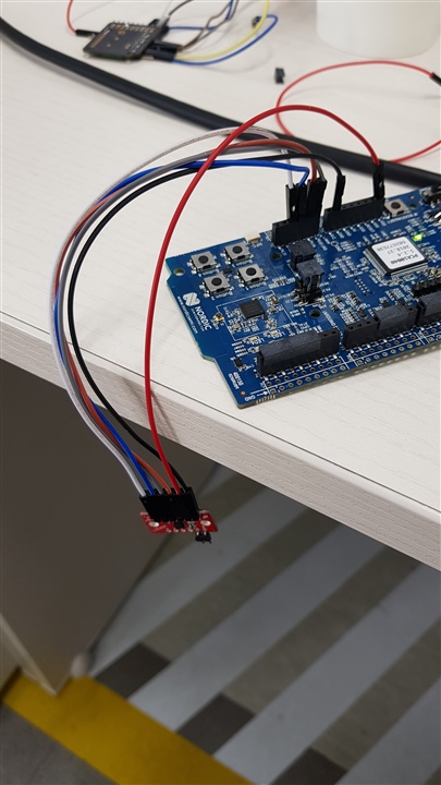
We currently developed codes by using nrf52832DK for nrf52810.

SPI was successful in the emulation and we have tried to transfer the code to the actual nrf52810 chip as the infocenter explained and correcting some bugs

emulating and transferring process:

https://infocenter.nordicsemi.com/index.jsp?topic=%2Fcom.nordic.infocenter.sdk5.v15.0.0%2Fnrf52810_user_guide.html&cp=4_0_0_5_0

correcting bugs: SPIM0 peripheral

https://devzone.nordicsemi.com/f/nordic-q-a/35145/crashing-during-the-spi-transfer-on-nrf52810

We thought that mapping the pins would be enough but it was not.

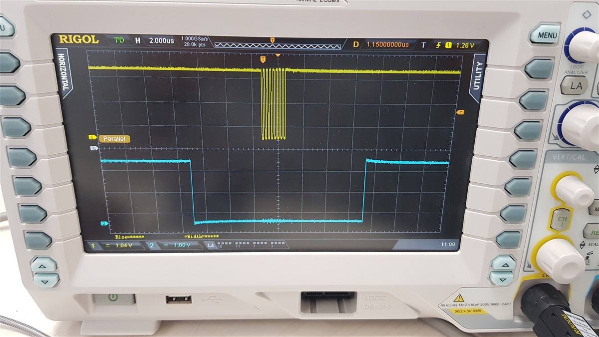
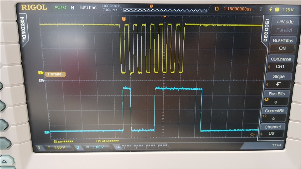
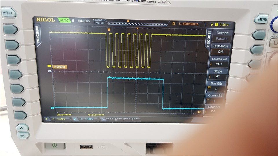
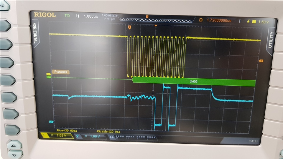
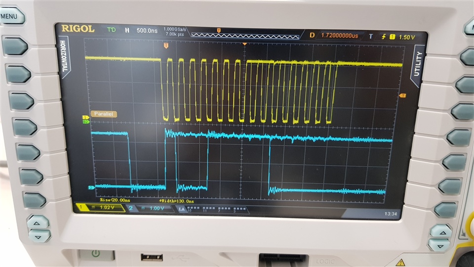
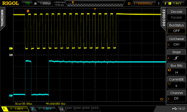
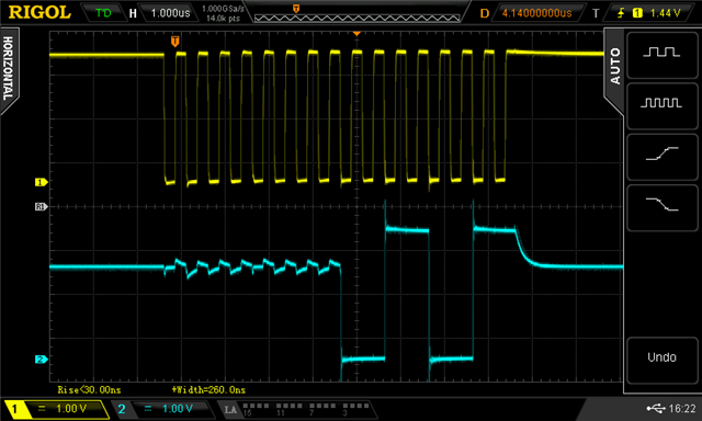
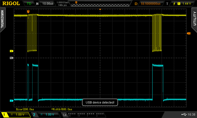
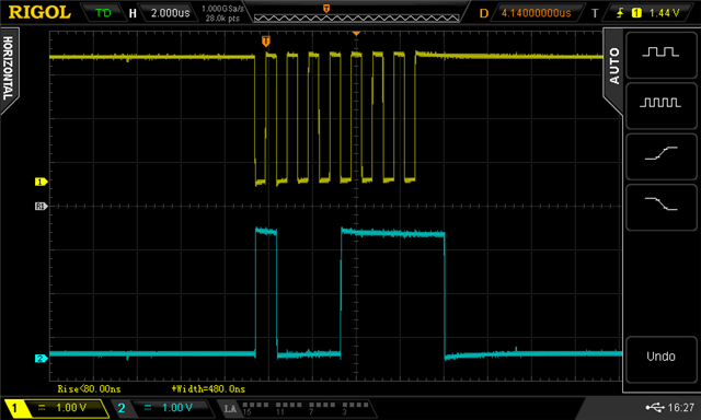
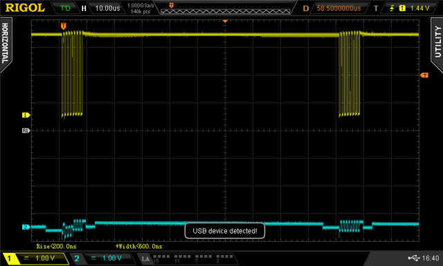
In emulation, reading the sensor was successful but in the actual nrf52810 environment, SPI reads only '0xff'

For double checking, blinking LED and BLE NUS was successful but the spi communication was failed.

How can we solve this problem?

Does the transferring procedure has some bug?

Parents
  • How can we solve this problem

    The first step is to see what's actually happening on the wires; eg, using an oscilloscope.

    And use the debugger to see what's happening in your code.

  • Thanks. Here is a schematic of our code

    #define SPI_INSTANCE	  0 /**< SPI instance index. */
    static const nrf_drv_spi_t spi = NRF_DRV_SPI_INSTANCE(SPI_INSTANCE);  /**< SPI instance. */
    static volatile bool spi_xfer_done;  /**< Flag used to indicate that SPI instance completed the transfer. */
    
    void spi_init(void)
    {
    nrf_drv_spi_config_t spi_config = NRF_DRV_SPI_DEFAULT_CONFIG;
    spi_config.ss_pin = 16;
    spi_config.miso_pin = 15;
    spi_config.mosi_pin = 14;
    spi_config.sck_pin = 12;
    spi_config.mode = NRF_DRV_SPI_MODE_3;
    spi_config.frequency = NRF_DRV_SPI_FREQ_4M;
    APP_ERROR_CHECK(nrf_drv_spi_init(&spi, &spi_config, spi_event_handler, NULL));
    }
    
    uint8_t SPI_Read(uint8_t cmd, uint8_t cmd_len, int delay)
    {
    memset(m_tx_buf,0,3);
    memset(m_rx_buf,0,4);
    
    m_tx_buf[0]=cmd;
    spi_xfer_done = false;
    APP_ERROR_CHECK(nrf_drv_spi_transfer(&spi, m_tx_buf, cmd_len,m_rx_buf, cmd_len));
    while(!spi_xfer_done); // sending command
    
    m_tx_buf[0]=0xFF;
    spi_xfer_done = false;
    APP_ERROR_CHECK(nrf_drv_spi_transfer(&spi, m_tx_buf, cmd_len,m_rx_buf, cmd_len));
    while(!spi_xfer_done);
    return m_rx_buf[0]; // reading recieved data
    }
    
    uint8_t LIS3DH_ReadID(void)
    {
    uint8_t ret, cmd;
    
    cmd=0x8F;
    ret=SPI_Read( cmd, 1,DELAY_MS);
    
    nrf_delay_ms(DELAY_MS);
    return m_rx_buf[0];
    }
    
    main{
    
    spi_init();
    
    LIS3DH_ReadID();
    
    	NRF_LOG_INFO("[HHC] LIS3DH ID = 0x%x.", sensorId); //returns 0xff  only..
    
    } 

  • I already used the breakpoints but couldn't find anything..

    I edited the source code.

    Using oscilloscope may give me some breakthroughs.

    I will reply later.

    My concern is that bugs exist in the SDK 15.0

  • These are capture of osciloscope of nrf53820

    SCK and CS:

    we used nrf_gpio_pin_set and nrf_gpio_pin_clear to handle the cs 

    SCK and MOSI : 

    We send the read command (0x8f and 0xff) but there is no response from the sensor

    These are signals of nrf52810 emulation

    SCK and MISO (successful to read 0x33)

    SCK and MOSI (sending 0x8f and 0xff)

    Even if the same source code, there are some difference in SCK signal

    I can't understand how to deal with it 

  • Plug a USB stick in here:

    and get proper screenshots from the scope!

  • IN nrf52810 emulation on nrf52832DK

    SCK and MOSI (sending 0x8f and 0xff)


    SCK and MISO (successful to read 0x33)

    In actual nrf52810

    SCK and MOSI (sending 0x8f and 0xff)

    there are a gap between sending 0x8f and 0xff

    mosi signal sending 0x8f for 8 clocks are shown below


    SCK and MISO

    there are no response from the sensor

  • That's so much clearer - isn't it?!

    Does your scope really only have 2 channels? Would be a lot easier to have SCK, MOSI, and MISO all together on the same screen!

    So your transmission looks OK, although the nRF52810 is adding a big gap between to 2 bytes. That shouldn't matter.

    But the MISO is not working in the nRF52810 case - it looks like something is pulling it down to ground?

    I seem to remember there was another thread recently with a similar problem ... ?

    Check your hardware.

    Try disconnecting MISO from the nRF52810, and measure at the Slave.

    Do the same with the nRF52832, for comparison.

Reply
  • That's so much clearer - isn't it?!

    Does your scope really only have 2 channels? Would be a lot easier to have SCK, MOSI, and MISO all together on the same screen!

    So your transmission looks OK, although the nRF52810 is adding a big gap between to 2 bytes. That shouldn't matter.

    But the MISO is not working in the nRF52810 case - it looks like something is pulling it down to ground?

    I seem to remember there was another thread recently with a similar problem ... ?

    Check your hardware.

    Try disconnecting MISO from the nRF52810, and measure at the Slave.

    Do the same with the nRF52832, for comparison.

Children
Related