This post is older than 2 years and might not be relevant anymore
More Info: Consider searching for newer posts

Question about nRF24L01

Hi,

After reading the nRF24L01 documentation, I have some questions regarding page 66 of the documentation (https://infocenter.nordicsemi.com/pdf/nRF24L01P_PS_v1.0.pdf?cp=8_4_0_0) :

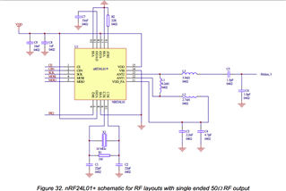
1. What are the chip inductors for and why the different values ?

2. What are the functions of the capacitors C3, C4, C5, C6, C7, C8 and C9 and why the values ? Are they all decoupling capacitors ?

3. Is the antenna the zigzagging yellow track next to the capacitors ? If yes, does its form matter for its radio frequency ?

4. What does "single ended 50Ω RF output" mean ?

Thanks in advance

  • 1. The components between ANT1/ANT2 forms the matching network. The topology and component value is chosen for optimal performance (output power, harmonic rejection and RX sensitivity). 

    2. Some are decoupling capacitors (larger values) and some are RF capacitors (smaller values, C4, C5 and C6)

    3. The antenna is not shown here, this should be connected to the point between C5 and C6. And yes, the shape and length does matter.

    4. This is where a monopole antenna is connected. 

Related