Hi,
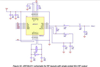
After reading the nRF24L01 documentation, I have some questions regarding page 66 of the documentation (https://infocenter.nordicsemi.com/pdf/nRF24L01P_PS_v1.0.pdf?cp=8_4_0_0) :
1. What are the chip inductors for and why the different values ?
2. What are the functions of the capacitors C3, C4, C5, C6, C7, C8 and C9 and why the values ? Are they all decoupling capacitors ?
3. Is the antenna the zigzagging yellow track next to the capacitors ? If yes, does its form matter for its radio frequency ?
4. What does "single ended 50Ω RF output" mean ?

Thanks in advance


