This post is older than 2 years and might not be relevant anymore
More Info: Consider searching for newer posts

Question about CPWG of nRF52840 Antenna

Hi
I am reviewing the nRF52840-DK hardware documentation to make boards with good antenna performance.

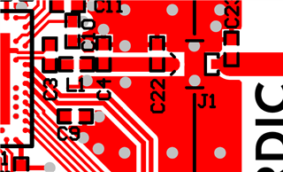
Q1. I have divided it into three areas as shown below. Is my understanding correct?

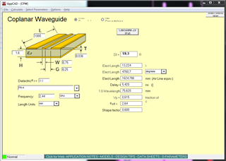
Q2. I found the following information in the document that I needed to calculate the CPWG.

Dielectric thickness = 1.4mm

Dk = 3.72

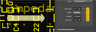
RF line width = 0.762mm

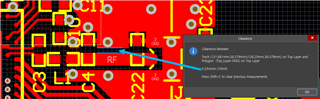
Clearance between RF line and GND = 0.254mm

I calculated the CPWG value from the link below.

http://www.rfdh.com/rfdb/cpwg.htm

The results are as follows.

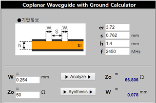
To obtain a 50 ohm line, W should be 0.078 mm. Calculated as 0.254mm according to the DK document, it becomes 66ohm.

Why is it made with 66ohm like the above?

Q3. I think the difference between 66ohm and 50ohm is compensated by C4 and C22 connected to the RF line. Am I right?

Q4. I'm going to make a 4-layer PCB (with a dielectric constant of 4.3) with 1.6T thickness. Can I make a CPWG with the same specifications as DK?

I'm looking forward to your reply.

Thanks

Parents
  • Hi,


    1. This is correct, C21 is a tuning cap for the antenna.
    2. Correct, the CPW impedance is not 50 ohms. This is an error in the design, but it works, just with slightly more RF loss between the nRF52840 and the antenna. Not sure exactly how much loss can be expected, maybe 0.5-1dB.
    3. No, C4 is part of the nRF52840 matching network, and C22 is NC. The line is 66 ohm.
    4. Absolutely, but as mentioned you might want to tweak the CPW dimensions such that the impedance is 50 ohm, meaning you will get the fill range performance from the nRF52840.


    Best regards,

    Andreas

Reply
  • Hi,


    1. This is correct, C21 is a tuning cap for the antenna.
    2. Correct, the CPW impedance is not 50 ohms. This is an error in the design, but it works, just with slightly more RF loss between the nRF52840 and the antenna. Not sure exactly how much loss can be expected, maybe 0.5-1dB.
    3. No, C4 is part of the nRF52840 matching network, and C22 is NC. The line is 66 ohm.
    4. Absolutely, but as mentioned you might want to tweak the CPW dimensions such that the impedance is 50 ohm, meaning you will get the fill range performance from the nRF52840.


    Best regards,

    Andreas

Children
  • Thank you for quick response.

    Compared to other boards I made, the nRF52840-DK showed high RSSI output.

    Also, when I look at the documentation of another development board (nRF52832-DK, Dongle and so on ..), the CPWG value I mentioned are almost similar.

    It seems a bit difficult to think of a design mistake. (Sorry if you are a design team.) Can you please confirm the above question to the antenna design team again?

  • Hi,


    No there definitely is a difference between nRF52832 DK and nRF52840 DK. As mentioned it is not critical, so you still see good performance with NRF52840 DK.


    nRF52832:


    nRF52840:

    Note how the nRF52840 does not have the wider section, which in nRF52832 is betwee C13 and J1.


    Best regards,

    Andreas

  • Thanks,

    I am going to make a board that adjusts impedance line width for testing.

    I will make board with 4 layer board.

    The layer stack is shown below.

    Layer 1

    prepreg / 0.2T / Dk = 4.18

    Layer 2

    core: 1.1T, Dk=4.3

    Layer 3

    prepreg / 0.2T / Dk = 4.18

    Layer 4

    And the pattern width of the impedance line will be 0.762mm same as DK,

    and the clearance with the ground on the side will be adjusted to 0.254mm(DK spec) -> 0.1mm.

    Q1. Please check if there is a problem when making the above specification.

    Q2. The PCB manufacturer says that the reference plane should be placed on the second or third floor near the impedance line on the first floor. However, DK has a reference plane on the fourth floor. Please comment on the above.

  • Hi,


    From what I can see thickness = 1.6mm, width~=0.75mm, gap~=0.25mm will give 50 ohm when the metal thickness is 0.1mm. With 0.036mm, which is a fairly common thickness, it is closer to 50 ohm. You should check what is specified for your PCB and adjust accordingly, if it is 0.1mm it will be fine.


    I am not sure what the PCB manufacturer is on about, for the CPW itself it is not important as long as you know that the substrate thickness will be different when calculating width and gap. With 0.2mm thickness between 3rd and 4th layer it is only minor though. One positive change might be that if using the 3rd layer, you will be able to use the 4th layer for other things, e.g. component placement.


    Best regards,

    Andreas

Related