This post is older than 2 years and might not be relevant anymore
More Info: Consider searching for newer posts

C6 and C13 values and function in nrf52810 reference design

Hi.

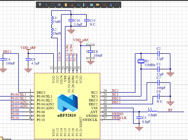
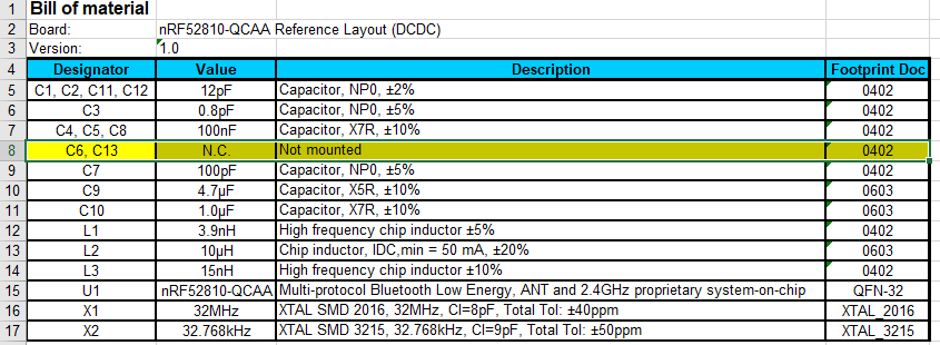
I'm using the nRF52810-QCAA (DCDC) Reference Design, but I've noticed that C6 and C13 are labeled as No Connected in both the schematic and BOM, but in the PCB model, they are actually mounted, why?

Can I safely remove them from my design or do I have to keep them?

Thanks in advance.
Parents
  • Hi Diego, 

    they are just illustrated as mounted in the design files, so that you get the solder pads for the capacitor on the pcb.  The N.C capacitor on DEC2 are put there for historical reasons, as there have been instances in earlier chips where the capacitor have been needed. So you can safely skip that, but when it comes to C13 that is still recommended to have. I can ask around for a specific values, but I would keep that one on the design. 

    Best regards,
    Kaja

Reply
  • Hi Diego, 

    they are just illustrated as mounted in the design files, so that you get the solder pads for the capacitor on the pcb.  The N.C capacitor on DEC2 are put there for historical reasons, as there have been instances in earlier chips where the capacitor have been needed. So you can safely skip that, but when it comes to C13 that is still recommended to have. I can ask around for a specific values, but I would keep that one on the design. 

    Best regards,
    Kaja

Children
Related