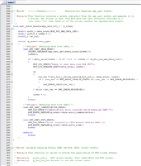
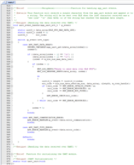
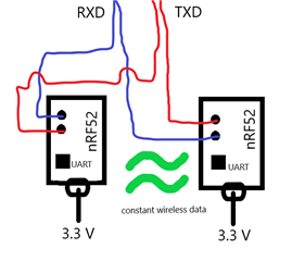
Hello, I am working on a project where I have 2 nRF52832 boards with the PCA10040. I have the example developer code examples. I am using the central and peripheral code examples to talk from one UART to another on Tera Term. Although, I noticed that this code is structured so that data is piled in an array and only sent to the other UART when I press "enter" or if it reaches a maximum size (which is very large). I am only using Tera Term to test my boards and not as part of the project. I have an external source of data that works properly on its own and am trying to use these UARTs to establish wireless communication. I have cut the solder bridges SB 22-25 to isolate PO.05 - PO.08 from nRF52832 to the Interface MCU. In pins 6 and 8 on both boards, I put TXD and RXD. Essentially what I am trying to do is have data go though the TXD & RXD wires to one UART, then wirelessly transfer data to the other UART, and have TXD & RXD wires come back. This processes will not work unless the code is structured so that data can be processed (sent & received) continuously. Or at least have it to where whatever is stacked up in the buffer is sent out every interval. I have attached the part of the code for both Central and Peripheral examples that specifically deal with data in UART. I have also put a diagram of sorts to help visualize. Any help would be great. Thanks.


