This post is older than 2 years and might not be relevant anymore
More Info: Consider searching for newer posts

I2C clock frequency problem

Hi,

I am using NRF52832 development board , to which i have interfaced LIS3DSH accelerometer sensor(3.3V i2c)

when i  configure it for 1600 sampling rate and all the axis enabled , i am not able to get any data .

could anyone help with this problem.

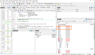
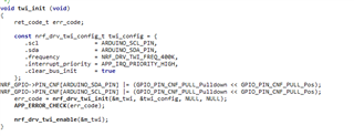
also the I2c clock frequency, as shown in below image, while i am capturing data when i observe in oscilloscope or logic analyzer , clock frequency is showing 200 all the setting is for 400KHz.

what could be the problem for this or is there any other way i need to follow to set the clock to 400KHz.
help me ASAP...

Thank you

Parents
  • "also the I2c clock frequency, as shown in below image, while i am capturing data when i observe in oscilloscope or logic analyzer , clock frequency is showing 200 all the setting is for 400KHz."
    That's unlikely, I think you're measuring the clock frequency incorrectly.


    Why have you enabled pulldowns on your IO pins?

  • actually that's not the part of code , sorry excluding that is the actual code

  • /**
     * Copyright (c) 2016 - 2018, Nordic Semiconductor ASA
     *
     * All rights reserved.
     *
     * Redistribution and use in source and binary forms, with or without modification,
     * are permitted provided that the following conditions are met:
     *
     * 1. Redistributions of source code must retain the above copyright notice, this
     *    list of conditions and the following disclaimer.
     *
     * 2. Redistributions in binary form, except as embedded into a Nordic
     *    Semiconductor ASA integrated circuit in a product or a software update for
     *    such product, must reproduce the above copyright notice, this list of
     *    conditions and the following disclaimer in the documentation and/or other
     *    materials provided with the distribution.
     *
     * 3. Neither the name of Nordic Semiconductor ASA nor the names of its
     *    contributors may be used to endorse or promote products derived from this
     *    software without specific prior written permission.
     *
     * 4. This software, with or without modification, must only be used with a
     *    Nordic Semiconductor ASA integrated circuit.
     *
     * 5. Any software provided in binary form under this license must not be reverse
     *    engineered, decompiled, modified and/or disassembled.
     *
     * THIS SOFTWARE IS PROVIDED BY NORDIC SEMICONDUCTOR ASA "AS IS" AND ANY EXPRESS
     * OR IMPLIED WARRANTIES, INCLUDING, BUT NOT LIMITED TO, THE IMPLIED WARRANTIES
     * OF MERCHANTABILITY, NONINFRINGEMENT, AND FITNESS FOR A PARTICULAR PURPOSE ARE
     * DISCLAIMED. IN NO EVENT SHALL NORDIC SEMICONDUCTOR ASA OR CONTRIBUTORS BE
     * LIABLE FOR ANY DIRECT, INDIRECT, INCIDENTAL, SPECIAL, EXEMPLARY, OR
     * CONSEQUENTIAL DAMAGES (INCLUDING, BUT NOT LIMITED TO, PROCUREMENT OF SUBSTITUTE
     * GOODS OR SERVICES; LOSS OF USE, DATA, OR PROFITS; OR BUSINESS INTERRUPTION)
     * HOWEVER CAUSED AND ON ANY THEORY OF LIABILITY, WHETHER IN CONTRACT, STRICT
     * LIABILITY, OR TORT (INCLUDING NEGLIGENCE OR OTHERWISE) ARISING IN ANY WAY OUT
     * OF THE USE OF THIS SOFTWARE, EVEN IF ADVISED OF THE POSSIBILITY OF SUCH DAMAGE.
     *
     */
    /** @file
     * @defgroup tw_scanner main.c
     * @{
     * @ingroup nrf_twi_example
     * @brief TWI Sensor Example main file.
     *
     * This file contains the source code for a sample application using TWI.
     *
     */
    
    #include <stdio.h>
    #include "boards.h"
    #include "app_util_platform.h"
    #include "app_error.h"
    #include "nrf_drv_twi.h"
    #include "nrf_delay.h"
    
    #include "LIS3DSH.h"
    #include "FFT.h"


    #include "nrf_log.h"
    #include "nrf_log_ctrl.h"
    #include "nrf_log_default_backends.h"
    #include "nrf_drv_gpiote.h"
    
    #include <stdbool.h>
    #include "nrf.h"
    #include "nrf_drv_gpiote.h"
    #include "app_error.h"
    #include "boards.h"
    #include "nrf_drv_timer.h"
    
    #include<stdio.h>
    
    #define APP_ERROR_CHECK1(ERR_CODE)                    \
            if (ERR_CODE != NRF_SUCCESS)                  \
            {                                              \
            	return ERR_CODE;                            \
            }
    
    
    /* TWI instance ID. */
    #if TWI0_ENABLED
    #define TWI_INSTANCE_ID     0
    #elif TWI1_ENABLED
    #define TWI_INSTANCE_ID     1
    #endif
    
     /* Number of possible TWI addresses. */
     #define TWI_ADDRESSES      127
    
    
     //#define MEMS_SENSOR_WHO_AM_I_ADDR      0x0F
    
    /* TWI instance. */
    static const nrf_drv_twi_t m_twi = NRF_DRV_TWI_INSTANCE(TWI_INSTANCE_ID);
    
    ret_code_t err_code = NRF_SUCCESS;
    
    uint16_t sampleCntTracker = 0x00;


    //typedef struct
    //{
    //   float fReal;
    //   float fImag;
    //}stXComplex;
    
    
    int16_t x_axis_data[SAMPLE_NUMBER] = {0x00};
    int16_t y_axis_data[SAMPLE_NUMBER] = {0x00};
    int16_t z_axis_data[SAMPLE_NUMBER] = {0x00};


    /**
     * @brief TWI initialization.
     */
    void twi_init (void)
    {
        ret_code_t err_code;
    
        const nrf_drv_twi_config_t twi_config = {
           .scl                = ARDUINO_SCL_PIN,
           .sda                = ARDUINO_SDA_PIN,
           .frequency          = NRF_DRV_TWI_FREQ_400K,
           .interrupt_priority = APP_IRQ_PRIORITY_HIGH,
           .clear_bus_init     = false
        };
    
        err_code = nrf_drv_twi_init(&m_twi, &twi_config, NULL, NULL);
        APP_ERROR_CHECK(err_code);
    
        nrf_drv_twi_enable(&m_twi);
    }
    
    ret_code_t readFromlis3dsh(uint8_t reg, uint8_t* p_dest, uint8_t bytes)
    {
        ret_code_t err = NRF_SUCCESS;
        err = nrf_drv_twi_tx(&m_twi, I2C_MEMS_SENSOR_BUS_ADDRESS, &reg, sizeof(reg), false);
        APP_ERROR_CHECK1(err);
        err = nrf_drv_twi_rx(&m_twi, I2C_MEMS_SENSOR_BUS_ADDRESS, p_dest, bytes);
        APP_ERROR_CHECK1(err);
        return NRF_SUCCESS;
    }
    
    ret_code_t writeTolis3dsh(uint8_t* const data, uint8_t bytes)
    {
        ret_code_t err = NRF_SUCCESS;
        err = nrf_drv_twi_tx(&m_twi, I2C_MEMS_SENSOR_BUS_ADDRESS, data, sizeof(data), false);
        APP_ERROR_CHECK1(err);
        return NRF_SUCCESS;
    }
    
    bool verifyLis3dshAccelerometer()
    {
        uint8_t verify = 0x00;
        readFromlis3dsh(MEMS_SENSOR_WHO_AM_I_ADDR, &verify, sizeof(verify));
        if(verify == MEMS_SENSOR_WHO_AM_I_VALUE)
        {
            return true;
        }
        return false;
    }
    
    ret_code_t noOfSamplesStoredinfifo(uint8_t* samplesCnt)
    {
        ret_code_t err = NRF_SUCCESS;
        err = readFromlis3dsh(MEMS_SENSOR_FIFO_SRC_ADDR, samplesCnt, sizeof(uint8_t));
        APP_ERROR_CHECK(err);
    }
    
    ret_code_t wakeUpStateMachineConfiguration()
    {
        ret_code_t err = NRF_SUCCESS;
        uint8_t toSend[2] = {0x00};
    
        toSend[0] = MEMS_SENSOR_CTRL_REG1_ADDR;
        toSend[1] = 0x01;
        err = writeTolis3dsh(toSend, sizeof(toSend));
        APP_ERROR_CHECK1(err);
    
        toSend[0] = MEMS_SENSOR_CTRL_REG3_ADDR;
        toSend[1] = 0x48;
        err = writeTolis3dsh(toSend, sizeof(toSend));
        APP_ERROR_CHECK1(err);
    
        toSend[0] = MEMS_SENSOR_CTRL_REG4_ADDR;
        toSend[1] = 0x97;/* 1.6k sampling rate is selected*/
        err = writeTolis3dsh(toSend, sizeof(toSend));
        APP_ERROR_CHECK1(err);
    
        toSend[0] = MEMS_SENSOR_CTRL_REG5_ADDR;
        toSend[1] = 0x00;
        err = writeTolis3dsh(toSend, sizeof(toSend));
        APP_ERROR_CHECK1(err);
    
        toSend[0] = THRS1_1;
        toSend[1] = 0x65;
        err = writeTolis3dsh(toSend, sizeof(toSend));
        APP_ERROR_CHECK1(err);
    
        toSend[0] = ST1_1;
        toSend[1] = 0x05;
        err = writeTolis3dsh(toSend, sizeof(toSend));
        APP_ERROR_CHECK1(err);
    
        toSend[0] = ST1_2;
        toSend[1] = 0x11;
        err = writeTolis3dsh(toSend, sizeof(toSend));
        APP_ERROR_CHECK1(err);
    
        toSend[0] = MASK1_B;
        toSend[1] = 0xFC;
        err = writeTolis3dsh(toSend, sizeof(toSend));
        APP_ERROR_CHECK1(err);
    
        toSend[0] = MASK1_A;
        toSend[1] = 0xFC;
        err = writeTolis3dsh(toSend, sizeof(toSend));
        APP_ERROR_CHECK1(err);
    
        toSend[0] = SETT1;
        toSend[1] = 0x01;
        err = writeTolis3dsh(toSend, sizeof(toSend));
        APP_ERROR_CHECK1(err);
    
        /* FIFO mode selection */
        memset(toSend, 0x00, sizeof(toSend));
        toSend[0] = MEMS_SENSOR_CTRL_REG6_ADDR;
        toSend[1] |= (FIFO_ENABLE | AUTO_ADDRESS_INCREMENT);
        err = writeTolis3dsh(toSend, sizeof(toSend));
        APP_ERROR_CHECK1(err);
    
        return NRF_SUCCESS;
    }
    
    int16_t two_compl_to_int16(uint16_t two_compl_value)
    {
        int16_t int16_value = 0;
    
        /* conversion */
        if (two_compl_value > 32768) {
            int16_value = (int16_t)(-(((~two_compl_value) & (uint16_t)(0xFFFF)) + (uint16_t)(1)));
        } else {
            int16_value = (int16_t)(two_compl_value);
        }
    
        return int16_value;
    }
    
    
    ret_code_t ReadOutputRegistersOfAccelerometerNew()
    {
        ret_code_t err = NRF_SUCCESS;
        uint8_t vibData[120] = {0x00};
    
        err = readFromlis3dsh(MEMS_SENSOR_OUT_X_L_ADDR, &vibData[0], sizeof(vibData));
        APP_ERROR_CHECK(err);
    
        for(uint16_t i = 0, j = 0; (j < SAMPLE_READ_ONE_ITERATION) && (i < (uint16_t)(SAMPLE_READ_ONE_ITERATION*6)) ; i = (uint16_t)(i+6), j++)
        {
            x_axis_data[sampleCntTracker + j] = two_compl_to_int16(((uint16_t)vibData[i+1]<<8) | (uint16_t)vibData[i]);
            y_axis_data[sampleCntTracker + j]= two_compl_to_int16(((uint16_t)vibData[i+3]<<8) | (uint16_t)vibData[i+2]);
            z_axis_data[sampleCntTracker + j] = two_compl_to_int16(((uint16_t)vibData[i+5]<<8) | (uint16_t)vibData[i+4]);
    
            x_axis_data[sampleCntTracker + j] = (int16_t)(x_axis_data[sampleCntTracker + j] * LIS3DSH_2G_SENSITIVITY);
            y_axis_data[sampleCntTracker + j] = (int16_t)(y_axis_data[sampleCntTracker + j] * LIS3DSH_2G_SENSITIVITY);
            z_axis_data[sampleCntTracker + j] = (int16_t)(z_axis_data[sampleCntTracker + j] * LIS3DSH_2G_SENSITIVITY);
        }
    
        sampleCntTracker = (uint16_t)(sampleCntTracker + SAMPLE_READ_ONE_ITERATION);
        return NRF_SUCCESS;
    }
    
    
    uint32_t timeCapture = 0x00;
    uint32_t time_ticks = 0x00;
    const nrf_drv_timer_t TIMER_LED = NRF_DRV_TIMER_INSTANCE(0);
    
    void startTimer()
    {
        uint32_t time_ms = 8000; //Time(in miliseconds) between consecutive compare events.
        nrf_drv_timer_config_t timer_cfg = NRF_DRV_TIMER_DEFAULT_CONFIG;
        err_code = nrf_drv_timer_init(&TIMER_LED, &timer_cfg, NULL);
        APP_ERROR_CHECK(err_code);
        time_ticks = nrf_drv_timer_ms_to_ticks(&TIMER_LED, time_ms);
    
        nrf_drv_timer_extended_compare(
             &TIMER_LED, NRF_TIMER_CC_CHANNEL0, time_ticks, NRF_TIMER_SHORT_COMPARE0_CLEAR_MASK, true);
        nrf_drv_timer_enable(&TIMER_LED);    
    }
    
    ret_code_t accelerometerDataAcquisition_SR_1_6_0_0(uint16_t sampleCount)
    {
        ret_code_t err = NRF_SUCCESS;
        uint8_t fifoSamples = 0x00;
    
        //startTimer();
        //nrf_delay_ms(50);
        //timeCapture = nrfx_timer_capture(&TIMER_LED, 0);
        //nrf_delay_us(ACC_DELAY_2_0);
        //nrf_delay_us(10000);
        //startTimer();
    
        nrf_delay_us(ACC_DELAY_2_0);
        err = noOfSamplesStoredinfifo(&fifoSamples);
        APP_ERROR_CHECK1(err);
        for(uint16_t it_cnt = 0x00; it_cnt < (sampleCount)/20; it_cnt++)
        {
            if(it_cnt)
            {
                nrf_delay_us(SEC_IT_DELAY_ODR_1_6_0_0);
            }
            err = ReadOutputRegistersOfAccelerometerNew();
            APP_ERROR_CHECK1(err);
        }
    //    err = FFT(N_DIRECTION_FFT, N_POINT_FFT, x_axis_data);
    //    if(err != SUCCESS)
    //    {
    //        return NRF_ERROR_INVALID_DATA;
    //    }
    //    err = FFT(N_DIRECTION_FFT, N_POINT_FFT, y_axis_data);
    //    if(err != SUCCESS)
    //    {
    //        return NRF_ERROR_INVALID_DATA;
    //    }
    //    err = FFT(N_DIRECTION_FFT, N_POINT_FFT, z_axis_data);
    //    if(err != SUCCESS)
    //    {
    //        return NRF_ERROR_INVALID_DATA;
    //    } 
          
        return NRF_SUCCESS;
    }
    
    void in_pin_handler(nrf_drv_gpiote_pin_t pin, nrf_gpiote_polarity_t action)
    {
        APP_ERROR_CHECK(NRF_LOG_INIT(NULL));
        NRF_LOG_DEFAULT_BACKENDS_INIT();
        NRF_LOG_INFO("INTERRUPT OCCURED");
        NRF_LOG_FLUSH();
    }
    
    ret_code_t wakeUpStateMachineInterruptConfiguration(void)
    {
        ret_code_t err = NRF_SUCCESS;
        nrf_drv_gpiote_in_config_t in_config = GPIOTE_CONFIG_IN_SENSE_TOGGLE(true);
        in_config.pull = NRF_GPIO_PIN_PULLUP;
        err = nrf_drv_gpiote_in_init(WAKE_UP_INT_PIN, &in_config, in_pin_handler);
        APP_ERROR_CHECK1(err);    
        nrf_drv_gpiote_in_event_enable(WAKE_UP_INT_PIN, true);
        return err;
    }


    //void timer_initializations()
    //{
    //
    //
    //    
    //}


    //const nrf_drv_timer_t TIMER_LED = NRF_DRV_TIMER_INSTANCE(0);
    
    int8_t address = 0x00;
    
    ret_code_t configureLis3dshAccelerometer()
    {
        ret_code_t err = NRF_SUCCESS;
        uint8_t reg[2] = {0x00};
        reg[0] = MEMS_SENSOR_CTRL_REG4_ADDR;
        reg[1] |= DATARATE_1600;
        err = writeTolis3dsh(&reg[0], sizeof(reg));
        APP_ERROR_CHECK(err);
    
        reg[0] = MEMS_SENSOR_CTRL_REG4_ADDR;
        reg[1] |= XYZ_ENABLE;
        err = writeTolis3dsh(&reg[0], sizeof(reg));
        APP_ERROR_CHECK(err);
    
        reg[0] = MEMS_SENSOR_CTRL_REG3_ADDR;
        reg[1] = 0x00;
        err = writeTolis3dsh(&reg[0], sizeof(reg));
        APP_ERROR_CHECK(err);
    
    
        reg[0] = MEMS_SENSOR_CTRL_REG5_ADDR;
        reg[1] |= FILTER_BW_800;
        err = writeTolis3dsh(&reg[0], sizeof(reg));
        APP_ERROR_CHECK(err);
    
        reg[0] = MEMS_SENSOR_CTRL_REG5_ADDR;
        reg[1] |= FULLSCALE_2;
        err = writeTolis3dsh(&reg[0], sizeof(reg));
        APP_ERROR_CHECK(err);
    
        reg[0] = MEMS_SENSOR_CTRL_REG5_ADDR;
        reg[1] |= (0x02 | SERIALINTERFACE_4WIRE);
        err = writeTolis3dsh(&reg[0], sizeof(reg));
        APP_ERROR_CHECK(err);
    
        reg[0] = MEMS_SENSOR_CTRL_REG6_ADDR;
        reg[1] |= (FIFO_ENABLE | AUTO_ADDRESS_INCREMENT);
        err = writeTolis3dsh(&reg[0], sizeof(reg));
        APP_ERROR_CHECK(err);
        
        reg[0] = MEMS_SENSOR_FIFO_CTRL_ADDR;
        //reg[1] |= FIFO_STREAM_MODE;
        reg[1]  = 0x54;
        err = writeTolis3dsh(&reg[0], sizeof(reg));
        APP_ERROR_CHECK(err);
        uint8_t no = 0x00;   
        err = noOfSamplesStoredinfifo(&no);
        APP_ERROR_CHECK(err);
    }
    
    /**
     * @brief Function for main application entry.
     */
    int main(void)
    {
        bool detected_device = false;
        ret_code_t err = NRF_SUCCESS;
    
        twi_init();
    
        detected_device = verifyLis3dshAccelerometer();
        if(!detected_device)
        {
              return 0;
        }
    
        err = configureLis3dshAccelerometer();
        APP_ERROR_CHECK(err);
    
        err = accelerometerDataAcquisition_SR_1_6_0_0(SAMPLE_NUMBER);
        APP_ERROR_CHECK(err);
        
        for(int i = 0 ; i < 10 ; i++)
        {
            printf("\t%d\t%d\t%d\n",x_axis_data[i],y_axis_data[i],z_axis_data[i]);
            NRF_LOG_FLUSH();
        
        }
        printf("GVR Sensor Moule Advertising.....");
          
        while(1)
        {
    //         nrf_pwr_mgmt_run();
        }
    }


    The above code is without softdevice enabled still the same issue, as u can see in line 129 400k is set

  • how did u say this macro in 944 th line is 400, isn't it how u set the clock.

  • If you use the 'default' config you can use sdk_config.h to choose the settings, but you can also just grab the settings definitions from the HAL. 

  • This code is a lot easier to read, thank you.

    I suggest you halt the CPU and read the TWI/TWIM registers. This will tell us what configuration is actually set in the TWI peripheral. If the FREQUENCY is set to 0x06680000 (400khz) then the root cause is most likely outside the MCU, and if it is not then the TWI peripheral has not been configured correctly in SW.

  • how to read TWI/TWIM registers, if not configured how to configure it.

Reply Children
Related