This post is older than 2 years and might not be relevant anymore
More Info: Consider searching for newer posts

I2C clock frequency problem

Hi,

I am using NRF52832 development board , to which i have interfaced LIS3DSH accelerometer sensor(3.3V i2c)

when i  configure it for 1600 sampling rate and all the axis enabled , i am not able to get any data .

could anyone help with this problem.

also the I2c clock frequency, as shown in below image, while i am capturing data when i observe in oscilloscope or logic analyzer , clock frequency is showing 200 all the setting is for 400KHz.

what could be the problem for this or is there any other way i need to follow to set the clock to 400KHz.
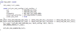
help me ASAP...

Thank you

Parents
  • "also the I2c clock frequency, as shown in below image, while i am capturing data when i observe in oscilloscope or logic analyzer , clock frequency is showing 200 all the setting is for 400KHz."
    That's unlikely, I think you're measuring the clock frequency incorrectly.


    Why have you enabled pulldowns on your IO pins?

  • actually that's not the part of code , sorry excluding that is the actual code

  • some form of loading on the I2C lines

    Which reminds me of the question asked several times early on in this thread - but I don't recall it ever being answered:

    Why have you enabled pulldowns on your IO pins

    Pulling-down the line is exactly what a Slave would do to stretch the clock ...

  • thanks and , i will check with them and let you know their response,

    tell me one more thing will pulling up the line help.

  • will pulling up the line help

    Who knows?

    It's your hardware - you need to do the debugging!

    Again, you need to use an oscilloscope to see what's actually happening in your hardware.

    Nobody else can do that for you.

    Your oscilloscope will show you if the rise time is too slow - ie, your pullups are not strong enough.

  • Thanks i know that i only have to do that , just asking your suggestion regarding that before i do anything which is not required.

  • As always - there's no point try to suggest cures before we know what the actual problem is!

    Scoping the signal is certainly not something that is "not required" - it should have been one of the very first things you did!

Reply
  • As always - there's no point try to suggest cures before we know what the actual problem is!

    Scoping the signal is certainly not something that is "not required" - it should have been one of the very first things you did!

Children
  • hi certainly , i have tested in oscilloscope before too , which also showed the same result as logic analyzer, in that i didn't check the parameters  such as rise time and etc., and it was done on pin 27 & 26 as a reference , i will redo it and will check again.

    Thank You 

  • But we didn't know that, and we can't see the results - can we?