This post is older than 2 years and might not be relevant anymore
More Info: Consider searching for newer posts

Modify NRF9160 at_client sample to run on external target PCB, with changed UART GPIO, and control through Link Monitor application.

We are moving to the stage of testing our custom PCB which has a nRF9160, from using the nRF9160 DK

We need to do initial tests on our antenna, tuning network, and layout, and our idea is to modify the at_client example to get various signal quality readings (RSRP, etc.) using the Link Monitor PC application.

To do this we need to figure out how to change the GPIO assignments in the at_client code to match our selected GPIO on the nRF9160 (TX on P0.11, and RX on P0.12).

The peripheral configuration for the part is very confusing, and I cannot figure out which files to modify in order to re-assign UART TX and RX pins.

Also, how do we interface to the Link Monitor application, since it looks like that is expecting a PCA10090 DK?

Thanks!

  • Hi,


    You need to do three things:

    1. Set the appropriate overlay in your application folder (nrf9160_pca10090ns.overlay)

    2. Set the appropriate overlay in the SPM (secure boot) project (nrf9160_pca10090.overlay)

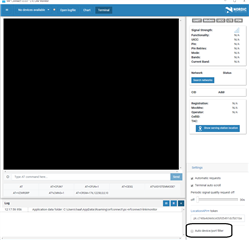
    3. Uncheck "Auto device/port filter" in LTE Link Monitor to be able to select your own COM interface.


    Overlaying SPM:

    * edit the file (append to it) ncs/nrf/samples/nrf9160/spm/nrf9160_pca10090.overlay to hold your configuration:

    &uart0 
    {
        status = "ok";
        tx-pin = <11>;
        rx-pin = <12>;
        /* disable by setting them to 0xffffffff */
    	rts-pin = <0xFFFFFFFF>;
    	cts-pin = <0xFFFFFFFF>;  
    };


    Overlaying your application:

    * Create the file ncs/nrf/samples/nrf9160/my_application/nrf9160_pca10090ns.overlay, which should contain this:

    &uart0 
    {
        status = "ok";
        tx-pin = <11>;
        rx-pin = <12>;
        /* disable by setting them to 0xffffffff */
    	rts-pin = <0xFFFFFFFF>;
    	cts-pin = <0xFFFFFFFF>;  
    };


    Uncheck in LTE Link monitor (may need to reset the application!):


    Now, you go into your application, and re-import it (to ensure that the new overlay settings are applied!) using a new build folder, and it should now route all uart0 traffic to the set pins.

    Let me know if there's any issues.


    Kind regards,

    Håkon

  • Håkon:

    Thanks for the quick reply, and the clear instructions!

    I was able to follow your steps and get our nRF9160 (with Hologram MFF2 SIM) on the network, using LTE Link Monitor.

    Once follow-up question:  Is there an easier way to change the TX/RX pin assignments, other than continually re-importing the application into SES, each time I change any peripheral pin assignrments?  It seems like a lot of work if I just change an ADC from P0.0 to P0.1.  It looks like editing the overlay files, even with a full clean/build, does not update the appropriate .dts_complied file.

    Regards,

    Jackson


  • Hi Jackson,


    Glad to hear that you were able to run everything as expected on your custom board.

    Jackson Wilson said:
    Is there an easier way to change the TX/RX pin assignments, other than continually re-importing the application into SES, each time I change any peripheral pin assignrments?  It seems like a lot of work if I just change an ADC from P0.0 to P0.1.  It looks like editing the overlay files, even with a full clean/build, does not update the appropriate .dts_complied file.

    You can edit the device tree directly in SES v4.18 (Project -> Edit Device Tree), but it is still required to re-import the project after changing anything here.

    This is only required if you change your pin-layout, or any other way change the device tree so that it needs updating.


    Kind regards,

    Håkon

  • Håkon:

    Thanks, I will pursue that.  One final question on the at_client project:

    Is there any tutorial on how the firmware for this project?  It is difficult to understand, from just examining the code, how the flow of processing AT commands works, since the "main()" function does almost nothing, and everything his handled in other source files (at_host.c, etc.).  It is not clear what peripherals are enabled, and what the flow of code execution is, if we want to debug, modify, or re-use any of this code.

    Thanks again for your help,

    Jackson


  • There's a library named "at_host.c" that runs in the background. This one gets initialized prior to main() being called.

    The at_host_init(), which is called, is here:

    https://github.com/NordicPlayground/fw-nrfconnect-nrf/blob/master/lib/at_host/at_host.c#L223


    This function sets up the UART and initializes a work-thread, cmd_send_work, which calls function "cmd_send()" when triggered from the UART RX interrupt handler.


    Most enabled libraries are initialized prior to your application being called, using this SYS_INIT() macro:

    https://github.com/NordicPlayground/fw-nrfconnect-nrf/blob/master/lib/at_host/at_host.c#L270


    The DEVICE_INIT and SYS_INIT macros are described in the zephyr documentation:

    https://docs.zephyrproject.org/latest/reference/drivers/index.html#system-drivers

    https://docs.zephyrproject.org/latest/reference/drivers/index.html#c.DEVICE_INIT


    Kind regards,

    Håkon

Related