This post is older than 2 years and might not be relevant anymore
More Info: Consider searching for newer posts

Modify NRF9160 at_client sample to run on external target PCB, with changed UART GPIO, and control through Link Monitor application.

We are moving to the stage of testing our custom PCB which has a nRF9160, from using the nRF9160 DK

We need to do initial tests on our antenna, tuning network, and layout, and our idea is to modify the at_client example to get various signal quality readings (RSRP, etc.) using the Link Monitor PC application.

To do this we need to figure out how to change the GPIO assignments in the at_client code to match our selected GPIO on the nRF9160 (TX on P0.11, and RX on P0.12).

The peripheral configuration for the part is very confusing, and I cannot figure out which files to modify in order to re-assign UART TX and RX pins.

Also, how do we interface to the Link Monitor application, since it looks like that is expecting a PCA10090 DK?

Thanks!

Parents
  • Hi,


    You need to do three things:

    1. Set the appropriate overlay in your application folder (nrf9160_pca10090ns.overlay)

    2. Set the appropriate overlay in the SPM (secure boot) project (nrf9160_pca10090.overlay)

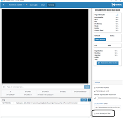
    3. Uncheck "Auto device/port filter" in LTE Link Monitor to be able to select your own COM interface.


    Overlaying SPM:

    * edit the file (append to it) ncs/nrf/samples/nrf9160/spm/nrf9160_pca10090.overlay to hold your configuration:

    &uart0 
    {
        status = "ok";
        tx-pin = <11>;
        rx-pin = <12>;
        /* disable by setting them to 0xffffffff */
    	rts-pin = <0xFFFFFFFF>;
    	cts-pin = <0xFFFFFFFF>;  
    };


    Overlaying your application:

    * Create the file ncs/nrf/samples/nrf9160/my_application/nrf9160_pca10090ns.overlay, which should contain this:

    &uart0 
    {
        status = "ok";
        tx-pin = <11>;
        rx-pin = <12>;
        /* disable by setting them to 0xffffffff */
    	rts-pin = <0xFFFFFFFF>;
    	cts-pin = <0xFFFFFFFF>;  
    };


    Uncheck in LTE Link monitor (may need to reset the application!):


    Now, you go into your application, and re-import it (to ensure that the new overlay settings are applied!) using a new build folder, and it should now route all uart0 traffic to the set pins.

    Let me know if there's any issues.


    Kind regards,

    Håkon

Reply
  • Hi,


    You need to do three things:

    1. Set the appropriate overlay in your application folder (nrf9160_pca10090ns.overlay)

    2. Set the appropriate overlay in the SPM (secure boot) project (nrf9160_pca10090.overlay)

    3. Uncheck "Auto device/port filter" in LTE Link Monitor to be able to select your own COM interface.


    Overlaying SPM:

    * edit the file (append to it) ncs/nrf/samples/nrf9160/spm/nrf9160_pca10090.overlay to hold your configuration:

    &uart0 
    {
        status = "ok";
        tx-pin = <11>;
        rx-pin = <12>;
        /* disable by setting them to 0xffffffff */
    	rts-pin = <0xFFFFFFFF>;
    	cts-pin = <0xFFFFFFFF>;  
    };


    Overlaying your application:

    * Create the file ncs/nrf/samples/nrf9160/my_application/nrf9160_pca10090ns.overlay, which should contain this:

    &uart0 
    {
        status = "ok";
        tx-pin = <11>;
        rx-pin = <12>;
        /* disable by setting them to 0xffffffff */
    	rts-pin = <0xFFFFFFFF>;
    	cts-pin = <0xFFFFFFFF>;  
    };


    Uncheck in LTE Link monitor (may need to reset the application!):


    Now, you go into your application, and re-import it (to ensure that the new overlay settings are applied!) using a new build folder, and it should now route all uart0 traffic to the set pins.

    Let me know if there's any issues.


    Kind regards,

    Håkon

Children
No Data
Related