This post is older than 2 years and might not be relevant anymore
More Info: Consider searching for newer posts

Optimizing PCB space with footprint size

Hi,

looking to nRF52832 reference PCB designs I've noticed that BOM contains different element sizes for different packages. Such, most of capacitors for QFN48 have 0402 footprint, when WLCSP suggests 0201. The same for crystals. So I'm thinking about saving some space with smaller packages.

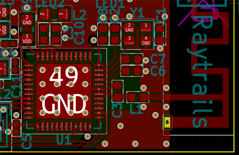
It's reasonable to avoid extra work recalculating the matching network and keep it intact. Also, replacing the 32MHz crystal (which itself is of the same footprint) capacitors won't really change anything:

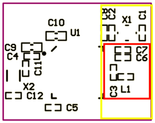
But how about other elements? Would it be safe to follow WLCSP BOM as a packaging guideline?

Also, for my understanding moving them won't affect RF performance, right?

Thanks!

Parents
  • Hi there,

    It's a little tricky to decipher what you've written, but in regards to RF performance, moving things around shouldn't affect RF performance appreciably.   If however your space saving exercise is with a view to ultimately shrink the overall board size - and hence the ground plane size - this will most certainly affect the RF performance.  Furthermore, the antenna trace will have been designed to exhibit a characteristic impedance at 2.4 GHz so pay attention to dielectric thickness, trace clearances, and physical continuity of the ground plane (and potentially omission of signal and power traces depending on how the board is stacked up) under the antenna trace.

    Whilst changes to the board means that the existing pi network will (almost certainly) be sub-optimal, how much so could vary and it may still work.  The safest bet in my view is to do your best to recreate the physical parameters relating to the antenna design of the existing antenna, test it in real life, and if the performance is not fit for purpose, you will most likely need to re-tune if the antenna.

    Good luck!

    Cheers,
    Z

  • Hi and thanks for the prompt reply!

    No, I'm not going to reduce board size - it's rather attempt to place my all other elements within my PCB constraints (roughly 17x28mm). Such, switching from 0402 to 0201 for C4, C5, C11, and C12, also to 0402 for C10, as well as employing 2012 package for X2 would save me some square mils for other components. At the same time I'm going to keep the reference design (including vias) for the yellow zone (please see my picture above).

    I understand that for the sake of simplicity the reference design tries to optimize the BOM too. So it it sounds like moving and sizing other components should not be an issue, I'll go for the experiment. Will keep you updated.

    By the way, the product specification says nothing about PCB thickness. What's the recommended value?

  • Hi Mike,

    first: our reference design is with a 1.6 mm thick FR4 pcb. 

    Changing the competent size of the component in the radio matching network, will most likely require that you tune the components values, but this is something that you usually have to do anyway, if you don't follow the reference design 1:1. 

    The components you have listed in the answer, will not effect the RF performance. 

    My best tips: Send us your design files, so that we can give you a proper review and advice, when you are done with the schematic and/or layout.

    We can also assist you on tuning matching network for the radio and antenna. 

    Best regards,
    Kaja

  • Hi zigenz!

    Yeah, I'm not following the reference design 1:1 (although I tried to) so expect some glitches when on air. Because RF is not the most critical part for me at the moment and there's some space for maneuvers later I'll probably go for the prototype and will check how bad I was at copy&paste :)

    And many thanks for the links!

  • Hi Kaja!

    I've ensured my design is 1.6 mm PCB. Thank you!

    I'm on the KiCAD so tried to re-create reference design as accurately as possible, however as you and zigenz pointed out there may be too many factors impacting the performance. The device is in prototyping stage, but as it goes further I'm interesting in doing comprehensive RF analysis. I'll appreciate if you could point me to what exactly I need to do in order to get it there.

    To get an idea what I'm doing the board figures are at http://gerblook.org/pcb/hkSbzZuF7ddHB3mzygbcsZ (board size is 17mm x 28 mm).

    And here is a hi-res version of the radio path:

  • Hi Mike, 

    from what I can see on the layout, I see that you are missing capacitors on P0.25 and P0.26, due errata 138. You could also use the alternative workaround, grounding the pins. 

    It would be beneficial to be able to give you a full review, if you could upload schematic and the gerber files. 
    --> if you would like them to be private, create a new ticket, private ticket, and just reference this case. 


    Best regards,
    Kaja

  • Yeah, sure. Here it is:

    [files were removed]

Reply Children
  • Have you used the antenna before? 

    You might need at least one shunt component, to help with impedance matching of the antenna. 

    The rest looks fine! 

    To test RF performance, see: whitepaper.
    For antenna tuning, see: whitepaper.

    Let me know if you don't have the right equipment.

    Best regards,
    Kaja

  • Hi Kaja,

    thank you a lot for the review!

    No, I haven't used the antenna to the day. It's designed to match 50 Ohm at 2.45 GHz so I hoped to do adjustments using the provided pi network. The section 53.7 of the product specification v4 also suggests to use it for antenna tuning. But after reading the DevZone far and wide (BTW those whitepapers are simply brilliant!) I found it seems rather recommended to keep the network intact and use additional pi-network for chip-antenna or, just like you noticed, a shunt component for a PCB. Thus I've put C15 (0402) as follows:

    Hope that the board will have acceptable performance for prototyping, but it would be nice to fine tune it and my other device in the end. For the second device (which is counterpart to this one) I'm not so constrained in space so will be able to preserve another LC for antenna. Unfortunately, have no equipment for that.

    Okay, so answering the original quesiton:

    1. reproduce nRF52 matching network area as close as possible to the reference design; not only values, but element sizes, placement, and vias matter.
    2. the reference pi network is designed for FR4 of 1.6 mm thick, 1 oz/ft^2
    3. either for PCB or chip-antennas keep space for their own pi network
    4. ensure ground plane is covering the radio path, do not route anything over it
    5. antenna feed line should obviously match 50 Ohm
    6. check power lines and pins near the radio - they shouldn't be the noise source
    7. other components which are not located near radio pins are free to change and move

    P.S. Thanks again for pointing to the P0.25 & P0.26 issue! I've terminated them with 12pF capacitors (again, overlooked that due to the outdated spec).

  • Great Mike! 

    We can help with tuning and RF measurements, it's a service we provide, you just have to cover the shipment cost. 

    So if you want you can send me two or three working PCB's and an sample enclosure, and I can do the measurements and tuning for you, when you have produce some boards.

    Best regards,
    Kaja

  • That's simply outstanding, thank you so much! I'm going to manufacture this board first, it's required for the second one. And after I'll be done with them both I'll be very glad to fine tune the radio. Thanks again!

  • Your welcome, 

    shipping information: 

    Mark the packet with the case ID(232469) and send it to:

    Nordic Semiconductor 
    Att: Kaja G. Sørbotten 
    Otto Nielsens vei 12
    7052 Trondheim
    Norway

    Just give me a heads up, when your sending it. 

    Best regards,
    Kaja

Related