Hi all,
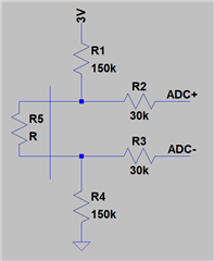
We are working on a project that requires us to measure the resistance of something applied externally. We are mainly interested in the change of resistance over time. It is possible to control the maximum resistance (default state) to some extend, and we have been asked by the supplier of this external part to define a maximum allowable resistance to have a clear reading between open circuit and the actual resistance value. You can find a draft of our intended circuit in the screenshot below.

The vertical line shows the interface, R5 is the external part. The values of R1-4 are specified because it will be a medical application. R1 and R4 are there to limit the current below 10µA in the case the two contacts going outside are being touched. The values for R2 and R3 are specified for the same purpose, but in single fault condition (limit is 50µA).
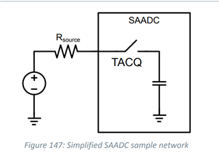
I read in the datasheet that the source resistance should be limited to 800k. The picture from the datasheet shows a single-ended ADC. I am a bit confused on how I can translate this to a differential ADC? Should I treat both differential inputs as single-ended input and calculate my worst case source resistance as 150k+R+30k (3V to ADC-)? If that is the case, it would mean that R can have a maximum value of 620k.

Is this correct, or am I missing something related to the differential usage of the ADC?
Thanks!


