Using the ble_app_uart example,
Using oscilloscope to measure the time interval of broadcasting, two development boards are used respectively.
One development board is nrf51422, the other is nrf52832.
Among them, nrf51422 uses an oscilloscope to measure the antenna, and the oscilloscope displays the accurate broadcast time interval.
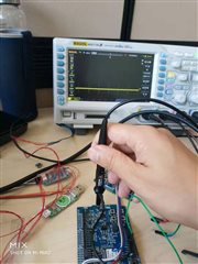
The nrf52832 development board does not show the broadcast interval in the same way as the oscilloscope.
The following figure
nrf52832
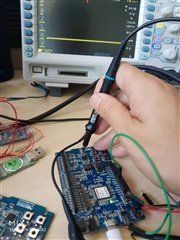
nrf51422