Hi,
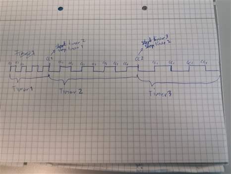
Experimenting on a stepper motor control (DRV8834). I want to be able to send a single square wave output, with a specified number of pulses. I managed to put together something that works ok using two timers and PPI after reading posts on DevZone. Now I need to find a way to modify this to achieve acceleration / decceleration. I would prefer in the same style using PPI if possible. Any suggestions?
typedef enum {
  MICROSTEP_1 = 1,
  MICROSTEP_2 = 2,
  MICROSTEP_4 = 4,
  MICROSTEP_8 = 8,
  MICROSTEP_16 = 16,
  MICROSTEP_32 = 32
}step_mode_t;

void move_linear(uint32_t travel_distance_um, uint32_t mm_per_sec, step_mode_t step_mode)
{
    const uint8_t step_len_um = 13;

    float nbr_pulses = (float)(travel_distance_um*step_mode)/step_len_um;
    uint32_t nbr_toggles = (uint32_t)(nbr_pulses*2);
    float pt_pulses_us = ((float)travel_distance_um*1000/mm_per_sec)/nbr_toggles;
    uint32_t timer_ticks_reload = (uint32_t)(pt_pulses_us / 0.0625) + 3;

    // Stop timers before change
    NRF_TIMER1->TASKS_STOP = 1;
    NRF_TIMER2->TASKS_STOP = 1;

    //Setup pulse out pin
    NRF_GPIOTE->CONFIG[0] = GPIOTE_CONFIG_MODE_Task << GPIOTE_CONFIG_MODE_Pos |
    GPIOTE_CONFIG_POLARITY_Toggle << GPIOTE_CONFIG_POLARITY_Pos |
    LED_1 << GPIOTE_CONFIG_PSEL_Pos |
    GPIOTE_CONFIG_OUTINIT_Low << GPIOTE_CONFIG_OUTINIT_Pos;

    //Setup pulse counter
    NRF_TIMER2->MODE = 1; //Counter mode
    NRF_TIMER2->BITMODE = 3; //32 bit
    NRF_TIMER2->TASKS_CLEAR = 1; //Clear counter value
    NRF_TIMER2->CC[1] = nbr_toggles; //Stop after <nbr> of pulses
    NRF_TIMER2->SHORTS = TIMER_SHORTS_COMPARE1_CLEAR_Enabled << TIMER_SHORTS_COMPARE1_CLEAR_Pos;

    //Setup pulse out timer
    NRF_TIMER1->MODE = 0; //Timer mode
    NRF_TIMER1->BITMODE = 3; //32 bit
    NRF_TIMER1->PRESCALER = 0; //16Mhz
    NRF_TIMER1->CC[1] = timer_ticks_reload;
    NRF_TIMER1->SHORTS = TIMER_SHORTS_COMPARE1_CLEAR_Enabled << TIMER_SHORTS_COMPARE1_CLEAR_Pos;

    //PPI connections
    NRF_PPI->CH[0].EEP = (uint32_t) &NRF_TIMER1->EVENTS_COMPARE[1]; // input = compare event of timer1
    NRF_PPI->CH[0].TEP = (uint32_t) &NRF_GPIOTE->TASKS_OUT[0]; // output = polarity toggle of the selected gpio
    NRF_PPI->FORK[0].TEP = (uint32_t) &NRF_TIMER2->TASKS_COUNT;
    NRF_PPI->CH[1].EEP = (uint32_t) &NRF_TIMER2->EVENTS_COMPARE[1]; // input = compare event of timer2
    NRF_PPI->CH[1].TEP = (uint32_t) &NRF_TIMER2->TASKS_CAPTURE[1];
    NRF_PPI->FORK[1].TEP = (uint32_t) &NRF_TIMER1->TASKS_STOP; //Stop pulse timer afer X pulses counted

    NRF_PPI->CHENSET = (PPI_CHENSET_CH0_Enabled << PPI_CHENSET_CH0_Pos);
    NRF_PPI->CHENSET = (PPI_CHENSET_CH1_Enabled << PPI_CHENSET_CH1_Pos);

    //*(uint32_t*)0x40009C0C = 1; // pan73_workaround
    NRF_TIMER2->TASKS_START = 1; // Start counter
    NRF_TIMER1->TASKS_START = 1; // Start timer
}

int main(void)
{
    move_linear(13, 10, MICROSTEP_16);
    while(1);
}
BR
//Ola

