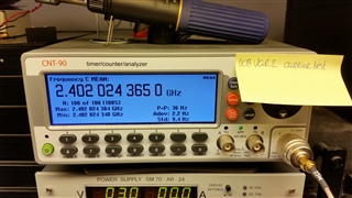
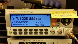
- Hardware: nRF52832
- SDK 14.2
- Segger Studio
Hello Sir or Madam,
We've made a new hardware variant of a previous design with an nRF52832 on much smaller form factor PCB. The customer for who it was designed however used an non-standard assembler and PCB manufacturere, who didn't follow the BOM as we had specified. Most of the new components and passive values where derivatives of the first design. For the 32kHz crystal and the 32MHz oscillator they used different components without telling the customers or asking for feedback on the selected components.
When I got the report that the devices didn't have stable BLE connections, I asked them for a few devices so I could test them.The devices could connect to my Samsung S5 with NRF Connect, but immediately disconnect with an "Error 8: GATT CONN TIMEOUT"
Reviewing the PCB I discovered that the 32kHz crystal and 32MHz oscillator where not the ones which were specified in the BOM. If I selected the 32MHz HFCLK as the source of the LF_CLK in the sdk_config.h file, BLE connection was stable for long periods of time. However the increased power consumption is not an option for this product, so I told the customer that the 32kHz should be replaced for the one which we specified (NX1610SA, previously NX33215SA on the first design). The 32MHz oscillator was replaced by a 10 ppm, 10pF load Cap ECS-320-10-48-CKY-TR, instead of the specified 20ppm, 8pF load cap NX1008AX.
When I got the reworked boards back the disconnect problem was still not completly resolved. I could connect with my S5, but still it would disconnect after 10 to 60 seconds. More modern mobile phones however are capable of maintaining a stable connection for a long duration (> 2 hours, I didn't bother to test any longer periods of time).
Suprised by the fact that the BLE connection was still not stable I searched on the Nordic forum and found a bit of code to measure the LF Clock frequency. I reworked it to the following:
int main(void)
{
    // Device parameters
    uint32_t  err_code;

    io_init();

    nrf_gpio_cfg_output(16);
    nrf_gpio_pin_write(16, 0);

    nrf_gpio_cfg_output(17);
    nrf_gpio_pin_write(17, 1);
    nrf_gpio_pin_write(17, 0);

    nrf_gpio_cfg_output(18);
    nrf_gpio_pin_write(18, 0);

    nrf_gpio_cfg_output(19);
    nrf_gpio_pin_write(19, 0);

	#if 0
	while(1)
	{
        nrf_gpio_pin_write(17, 1);
		nrf_delay_ms(1000);
		nrf_gpio_pin_write(17, 0);
        nrf_delay_ms(1000);
	}
	#endif


	err_code = nrf_pwr_mgmt_init();
	APP_ERROR_CHECK(err_code);

    // Start 32 kHz clock
    NRF_CLOCK->TASKS_HFCLKSTOP	= 1;
	NRF_CLOCK->LFCLKSRC			= 2; // 0=RC, 1=Xtal, 2=Synth from 32MHz
	NRF_CLOCK->TASKS_LFCLKSTART = 1;

	// Configure GPIOTE to toggle gpio 0
	NRF_GPIOTE->CONFIG[0] = (GPIOTE_CONFIG_MODE_Task       << GPIOTE_CONFIG_MODE_Pos)     |
							(GPIOTE_CONFIG_OUTINIT_Low     << GPIOTE_CONFIG_OUTINIT_Pos)  |
							(GPIOTE_CONFIG_POLARITY_Toggle << GPIOTE_CONFIG_POLARITY_Pos) |
							(17                            << GPIOTE_CONFIG_PSEL_Pos);

	// Configure RTC1 to generate tick event
	NRF_RTC1->PRESCALER = 0;
	NRF_RTC1->EVTENSET  = RTC_EVTENSET_TICK_Msk;

	// Connect RTC1 tick event to GPIOTE toggle task
	NRF_PPI->CH[0].EEP = (uint32_t) &NRF_RTC1->EVENTS_TICK;
	NRF_PPI->CH[0].TEP = (uint32_t) &NRF_GPIOTE->TASKS_OUT[0];
	NRF_PPI->CHEN      = PPI_CHENCLR_CH0_Msk;

	// Start RTC1
	NRF_RTC1->TASKS_START = 1;


    // Enter main loop.
    for (;;)
    {


    }
}
The code above toggles pin 17 every rising edge of the 32kHz oscillator, so effectively the output frequency is half that of the LF_CLK_SRC. The LF_CLK_SRC was set to 32MHz or to the external 32kHz oscillator.
I used this code to measure the frequency of the LF_CLK source for the following configurations:
- PCB variant 2 V1 with LF_CLK=SYNTH 32MHz ECS-320-10-48-CKY-TR
- PCB variant 2 V1 with LF_CLK= XTAL 32kHz NX1610SA
- PCB variant 1 V4 with LF_CLK= XTAL 32kHz NX33215SA
The frequency counter counted the following:
PCB variant 2 V1 with LF_CLK=SYNTH 32MHz ECS-320-10-48-CKY-TR
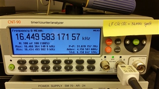
LF_Frequency = 32.89916634 kHz, dF= 131.16634 Hz
PCB variant 2 V1 with reworked LF_CLK= XTAL 32kHz NX1610SA:
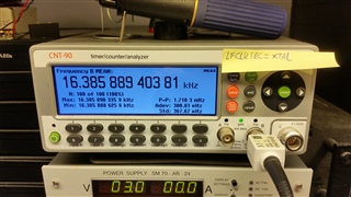
LF_Frequency = 32.77177881 kHz, dF= 3.77881 Hz
PCB variant 1 V4 with LF_CLK= XTAL 32kHz NX33215SA
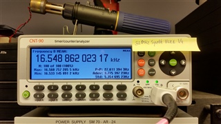
LF_Frequency = 33.09772405 kHz, dF= 329.72405 Hz
So despite the fact that the reworked PCB variant 2 V1 has the lowest frequency error (from 32768Hz) and the lowest peak-peak value compared to the synth frequencies for both PCB variants, BLE doesn't work properly with older smartphones.
I must note that the variant 1 PCB's antenne has been tuned, and variant 2 has not been tuned due to a different potting compound being selected depending on test results. However the signal strenght (-70 dBm nRF Connect App S5) should still be sufficient for short range (< 50 cm) with said S5, especially when the ble communication is stable with the 32MHz synth selected as LF_CLK_SRC.
So my questions are as following:
- Why does the BLE communication not work properly with the NX1610SA as low frequency source, despite it being superior in frequency error and stability?
- How important is the antenna tuning, despite the fact that with the 32MHz synth selected as LF source the ble communication is stable?
- How important is the frequency tuning by selecting the capacitors in parallel with the clock and oscillators? In the first PCB version it all "worked" stable, so we never bothered to try different capacitor values. Seeing how BLE does work when off the target frequency of 32.768kHz it makes me wonder how important this actually is.


