This post is older than 2 years and might not be relevant anymore
More Info: Consider searching for newer posts

BLE GATT CONN TIMEOUT 32kHz xtal

  • Hardware: nRF52832
  • SDK 14.2
  • Segger Studio

Hello Sir or Madam,

We've made a new hardware variant of a previous design with an nRF52832 on much smaller form factor PCB. The customer for who it was designed however used an non-standard assembler and PCB manufacturere, who didn't follow the BOM as we had specified. Most of the new components and passive values where derivatives of the first design. For the 32kHz crystal and the 32MHz oscillator they used different components without telling the customers or asking for feedback on the selected components.

When I got the report that the devices didn't have stable BLE connections, I asked them for a few devices so I could test them.The devices could connect to my Samsung S5 with NRF Connect, but immediately disconnect with an "Error 8: GATT CONN TIMEOUT"

Reviewing the PCB I discovered that the 32kHz crystal and 32MHz oscillator where not the ones which were specified in the BOM. If I selected the 32MHz HFCLK as the source of the LF_CLK in the sdk_config.h file, BLE connection was stable for long periods of time. However the increased power consumption is not an option for this product, so I told the customer that the 32kHz should be replaced for the one which we specified (NX1610SA, previously NX33215SA on the first design). The 32MHz oscillator was replaced by a 10 ppm, 10pF load Cap ECS-320-10-48-CKY-TR, instead of the specified 20ppm, 8pF load cap NX1008AX.

When I got the reworked boards back the disconnect problem was still not completly resolved. I could connect with my S5, but still it would disconnect after 10 to 60 seconds. More modern mobile phones however are capable of maintaining a stable connection for a long duration (> 2 hours, I didn't bother to test any longer periods of time).

Suprised by the fact that the BLE connection was still not stable I searched on the Nordic forum and found a bit of code to measure the LF Clock frequency. I reworked it to the following:

int main(void)
{
    // Device parameters
    uint32_t  err_code;

    io_init();  

    nrf_gpio_cfg_output(16);
    nrf_gpio_pin_write(16, 0);

    nrf_gpio_cfg_output(17);
    nrf_gpio_pin_write(17, 1);
    nrf_gpio_pin_write(17, 0);

    nrf_gpio_cfg_output(18);
    nrf_gpio_pin_write(18, 0);

    nrf_gpio_cfg_output(19);
    nrf_gpio_pin_write(19, 0);

	#if 0
	while(1)
	{
        nrf_gpio_pin_write(17, 1);
		nrf_delay_ms(1000);
		nrf_gpio_pin_write(17, 0);
        nrf_delay_ms(1000);
	}
	#endif


	err_code = nrf_pwr_mgmt_init();
	APP_ERROR_CHECK(err_code);

    // Start 32 kHz clock
    NRF_CLOCK->TASKS_HFCLKSTOP	= 1;
	NRF_CLOCK->LFCLKSRC			= 2; // 0=RC, 1=Xtal, 2=Synth from 32MHz
	NRF_CLOCK->TASKS_LFCLKSTART = 1;

	// Configure GPIOTE to toggle gpio 0
	NRF_GPIOTE->CONFIG[0] = (GPIOTE_CONFIG_MODE_Task       << GPIOTE_CONFIG_MODE_Pos)     | 
							(GPIOTE_CONFIG_OUTINIT_Low     << GPIOTE_CONFIG_OUTINIT_Pos)  |
							(GPIOTE_CONFIG_POLARITY_Toggle << GPIOTE_CONFIG_POLARITY_Pos) | 
							(17                            << GPIOTE_CONFIG_PSEL_Pos);

	// Configure RTC1 to generate tick event
	NRF_RTC1->PRESCALER = 0;
	NRF_RTC1->EVTENSET  = RTC_EVTENSET_TICK_Msk;

	// Connect RTC1 tick event to GPIOTE toggle task
	NRF_PPI->CH[0].EEP = (uint32_t) &NRF_RTC1->EVENTS_TICK;
	NRF_PPI->CH[0].TEP = (uint32_t) &NRF_GPIOTE->TASKS_OUT[0];
	NRF_PPI->CHEN      = PPI_CHENCLR_CH0_Msk;
                     
	// Start RTC1
	NRF_RTC1->TASKS_START = 1;
 
 
    // Enter main loop.
    for (;;)
    {
        

    }
}

The code above toggles pin 17 every rising edge of the 32kHz oscillator, so effectively the output frequency is half that of the LF_CLK_SRC. The LF_CLK_SRC was set to 32MHz or to the external 32kHz oscillator.

I used this code to measure the frequency of the LF_CLK source for the following configurations:

  1. PCB variant 2 V1 with LF_CLK=SYNTH 32MHz ECS-320-10-48-CKY-TR
  2. PCB variant 2 V1 with LF_CLK= XTAL 32kHz NX1610SA
  3. PCB variant 1 V4 with LF_CLK= XTAL 32kHz NX33215SA 

The frequency counter counted the following:

PCB variant 2 V1 with LF_CLK=SYNTH 32MHz ECS-320-10-48-CKY-TR
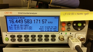
LF_Frequency = 32.89916634 kHz, dF= 131.16634 Hz

PCB variant 2 V1 with reworked LF_CLK= XTAL 32kHz NX1610SA:
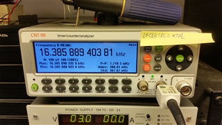
LF_Frequency = 32.77177881 kHz, dF= 3.77881 Hz

PCB variant 1 V4 with LF_CLK= XTAL 32kHz NX33215SA
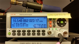
LF_Frequency = 33.09772405 kHz, dF= 329.72405 Hz

So despite the fact that the reworked PCB variant 2 V1 has the lowest frequency error (from 32768Hz) and the lowest peak-peak value compared to the synth frequencies for both PCB variants, BLE doesn't work properly with older smartphones.

I must note that the variant 1 PCB's antenne has been tuned, and variant 2 has not been tuned due to a different potting compound being selected depending on test results. However the signal strenght (-70 dBm nRF Connect App S5) should still be sufficient for short range (< 50 cm) with said S5, especially when the ble communication is stable with the 32MHz synth selected as LF_CLK_SRC.

So my questions are as following:

  1. Why does the BLE communication not work properly with the NX1610SA as low frequency source, despite it being superior in frequency error and stability?
  2. How important is the antenna tuning, despite the fact that with the 32MHz synth selected as LF source the ble communication is stable?
  3. How important is the frequency tuning by selecting the capacitors in parallel with the clock and oscillators? In the first PCB version it all "worked" stable, so we never bothered to try different capacitor values. Seeing how BLE does work when off the target frequency of 32.768kHz it makes me wonder how important this actually is.

Parents
  • Hi,


    1. Hard to say. What ppm do you configure when you enable the Softdevice? Even though the crystal should be more than accurate enough you might want to keep some headroom.

    2. The antenna tuning determines how much energy is transferred between to and from the PCB, from a propagating wave on air. Poorly tuned means less energy is transferred, but provided the units are not moving and there is not a whole lot of change in the environment, should stay more or less constant. 

    3. The values of the caps determine the frequency at which the crystal oscillates, so you need to measure and see which values brings you the closest (least error), and configure the Softdevice with the according accuracy, preferably with some margin.


    Best regards,

    Andreas

  • Hello Andreas,

    1.The crystal is 20 PPM, so I've configured the SDK with:

    // <0=> NRF_CLOCK_LF_XTAL_ACCURACY_250_PPM 
    // <1=> NRF_CLOCK_LF_XTAL_ACCURACY_500_PPM 
    // <2=> NRF_CLOCK_LF_XTAL_ACCURACY_150_PPM 
    // <3=> NRF_CLOCK_LF_XTAL_ACCURACY_100_PPM 
    // <4=> NRF_CLOCK_LF_XTAL_ACCURACY_75_PPM 
    // <5=> NRF_CLOCK_LF_XTAL_ACCURACY_50_PPM 
    // <6=> NRF_CLOCK_LF_XTAL_ACCURACY_30_PPM 
    // <7=> NRF_CLOCK_LF_XTAL_ACCURACY_20_PPM 
    
    
    #define NRF_SDH_CLOCK_LF_XTAL_ACCURACY 7

    I've tried 50ppm, but then the softdevice doesn't start.

    2 & 3. Okay, thats what I expected. It however doesn't explain why the synth frequency on both boards is way off the expected frequency of 32768Hz, but BLE still works while with the new crystal which is only a few hertz off-frequency BLE works only for a short period.

    I think I'll measure the nRF52832 devkit with the code I posted and measure the frequency for both the XTAL and SYNTH modes, so I can compare the results with the previous measurements.

    Might there be some connection/correlation between the 32MHz and the 32kHz clocks which might not work well with the combination of components? I have the softdevice RC calibration timer set to 0 since I do not use the RC timer, but is there something else like this which uses both clock sources?

    What's the best method to measure the 32MHz clock? This might reveal something.

Reply
  • Hello Andreas,

    1.The crystal is 20 PPM, so I've configured the SDK with:

    // <0=> NRF_CLOCK_LF_XTAL_ACCURACY_250_PPM 
    // <1=> NRF_CLOCK_LF_XTAL_ACCURACY_500_PPM 
    // <2=> NRF_CLOCK_LF_XTAL_ACCURACY_150_PPM 
    // <3=> NRF_CLOCK_LF_XTAL_ACCURACY_100_PPM 
    // <4=> NRF_CLOCK_LF_XTAL_ACCURACY_75_PPM 
    // <5=> NRF_CLOCK_LF_XTAL_ACCURACY_50_PPM 
    // <6=> NRF_CLOCK_LF_XTAL_ACCURACY_30_PPM 
    // <7=> NRF_CLOCK_LF_XTAL_ACCURACY_20_PPM 
    
    
    #define NRF_SDH_CLOCK_LF_XTAL_ACCURACY 7

    I've tried 50ppm, but then the softdevice doesn't start.

    2 & 3. Okay, thats what I expected. It however doesn't explain why the synth frequency on both boards is way off the expected frequency of 32768Hz, but BLE still works while with the new crystal which is only a few hertz off-frequency BLE works only for a short period.

    I think I'll measure the nRF52832 devkit with the code I posted and measure the frequency for both the XTAL and SYNTH modes, so I can compare the results with the previous measurements.

    Might there be some connection/correlation between the 32MHz and the 32kHz clocks which might not work well with the combination of components? I have the softdevice RC calibration timer set to 0 since I do not use the RC timer, but is there something else like this which uses both clock sources?

    What's the best method to measure the 32MHz clock? This might reveal something.

Children
  • Hi,


    I see no reason why the softdevice should not start with higher accuracy configuration. This just instructs how to widen the RX windows. Does either of the even higher allow it to start?

    The synth being off indicates that the 32 MHz crystal is also inaccurate. Have you measured the accuracy of this (frequency accuracy of unmodulated TX carrier using a spectrum analyzer)? If my calculations are correct, the deviation you are seeing is 10k ppm (!) with such an offset there will not be any radio activity.

    I tested your code with a logic analyzer on a DK, although probably as accurate as your counter it seems accurate enough to distinguish a difference between RC and crystal/synth.


    Not sure I understand what you mean about the correlation between the clocks, but no there should not be any other similar settings or anything which you need to set.


    32 MHz crystal should be measured by looking at a TX carrier, as mentioned above.


    Best regards,

    Andreas

  • Hello Andreas,

    I've measured both an nRF52832 devkit as an PCB variant 2's HF CLK frequency with the DTM example in the SDK. I've hardcoded the nRF mcu to output an onmodulated carrier on the antenna with the following piece of modified example main code:

    int main(void)
    {
        uint32_t    current_time;
        uint32_t    dtm_error_code;
        uint32_t    msb_time          = 0;     // Time when MSB of the DTM command was read. Used to catch stray bytes from "misbehaving" testers.
        bool        is_msb_read       = false; // True when MSB of the DTM command has been read and the application is waiting for LSB.
        uint16_t    dtm_cmd_from_uart = 0;     // Packed command containing command_code:freqency:length:payload in 2:6:6:2 bits.
        uint8_t     rx_byte;                   // Last byte read from UART.
        dtm_event_t result;                    // Result of a DTM operation.
    
      //  io_init();
    
        bsp_board_leds_init();
        
        //uart_init();
    
        dtm_error_code = dtm_init();
        if (dtm_error_code != DTM_SUCCESS)
        {
            // If DTM cannot be correctly initialized, then we just return.
            return -1;
        }
    
        dtm_cmd_put(0xC000); // STOP
        dtm_cmd_put(0x800B); // TXpwr 0dBm
        dtm_cmd_put(0x8003); // TX carrier test
    
        for (;;)
        {
      
        }
    }

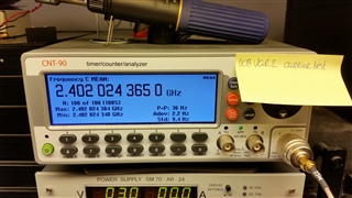
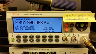
    Both devices measured an accurate carrier frequency when set on 2.402 GHz.

    PCB variant 2: +24,3 kHz

    nRF52832 devkit: -9.2kHz

    So I must conclude that both frequencies look fine.

    The synth being off indicates that the 32 MHz crystal is also inaccurate. Have you measured the accuracy of this (frequency accuracy of unmodulated TX carrier using a spectrum analyzer)? If my calculations are correct, the deviation you are seeing is 10k ppm (!) with such an offset there will not be any radio activity.

    I think measuring the LF CLK output in order to measure the HF CLK frequency is very inaccurate. I don't know why the synthesized LF clock is so off-frequency compared to normal XTAL operation.

    Not sure I understand what you mean about the correlation between the clocks, but no there should not be any other similar settings or anything which you need to set.

    What I meant to ask was: if there was some some sort of timing calibration being done with the 32MHz to calibrate or manage the timeslots with the 32kHz crystal. If the 32MHz oscillator was off-frequency, this would influence the timing based on the 32kHz crystal and might explain the missed timeslots.

    I've tried 50ppm, but then the softdevice doesn't start.

    I tested on a different device with the PPM settings of the LF CLK and it seems that this unit works with higher PPM settings. With 50 ppm the connection no longer disconnects.

    It seems that the LF CLK is the cause of the problem. Might the manual rework have influenced the crystals performance so serverly that it went from 20ppm to ~50ppm? Or might this be an issue of the load capacitors of the crystal? We always use NP0/C0G, but since we don't have any information what the assembler has used, could the capacitor tolerance be the cause of this issue?

    I'll order some parts and rework the components of the 32kHz crystal.

  • Hi,


    OK, both 9 kHz and 24 kHz is satiable offsets for the 32 MHz clock, and way more accurate than the synthesized 32kHz. Now that I think about it, you actually do not start the HFCLK in your test code, I do not know if the 32MHz crystal starts automatically and I am not able to test it now. Try issuing

        NRF_CLOCK->TASKS_HFCLKSTART    = 1;
    
        // Wait for the external oscillator to start up.
        while (NRF_CLOCK->EVENTS_HFCLKSTARTED == 0)
        {
            // Do nothing.
        }

     before 

    	NRF_CLOCK->TASKS_LFCLKSTART = 1;


    Anyway as the link seems to survive with 50ppm accuracy setting this might not be relevant anymore. It's hard to say why the accuracy is so different in the boards that are differently populated from your assembler, but swapping an E12 value further away (or similarly changing CL of the crystal) tends to change the frequency offset 10-20 ppm. NP0 caps shall not vary over temperature, but if the primary tolerance is too large, say > 10%, you might see 10-20ppm variation solely from these.


    Best regards,

    Andreas

Related