Beware that this post is related to an SDK in maintenance mode
More Info: Consider nRF Connect SDK for new designs
This post is older than 2 years and might not be relevant anymore
More Info: Consider searching for newer posts

SAADC reading changes after system finish booting

Hi everyone,

I am having problems reading the battery level using the SAADC. The main problem is that the reading is not consistent from when the device is booting to once the device has boot completely an is stable/IDLE. 

During the initialization the reading is around 4.2 V for battery totally charged while later it drops to around 3.6 V.

Hardware Configuration:

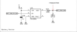
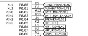
To read the battery, I have a voltage divider connected to the AIN0 pin for reading the battery voltage. The resistor pulled to ground is 51K ohms while the one pulled to VBAT is 100k ohms. I had checked the voltage across both resistor with a multimeter and it stays consistent the whole time. So, it seems like a software problem.

Software Configuration:

For reading the battery, I am using a simple blocking approach using the SAADC in single mode in the pin AIN0. The SAADC is configured as:

   // SAADC configuration
    nrf_drv_saadc_config_t saadc_config;           
    saadc_config.low_power_mode = true;
    saadc_config.resolution = SAADC_RESOLUTION;
    saadc_config.oversample = SAADC_OVERSAMPLE;
    
    // SAADC CHANNEL configuration
    channel_config.gain = NRF_SAADC_GAIN1_6;
    channel_config.reference = NRF_SAADC_REFERENCE_INTERNAL;
    channel_config.acq_time = NRF_SAADC_ACQTIME_20US;
    channel_config.burst = SAADC_BURST_MODE;
    err_code = nrf_drv_saadc_channel_init(0, &channel_config);              // Init SAADC channel

and then use the simple function `nrf_drv_saadc_sample_convert()` to read the battery, like:

    nrf_saadc_value_t value;
    ret_code_t err_code;
    
    saadc_init(false);
    
    err_code = nrf_drv_saadc_sample_convert(0, &value);
    APP_ERROR_CHECK(err_code);

    saadc_uninit();


The oversampling and burst are currently disable, but I had tried those to with same result. I had also tried calibrate before the reading, use a buffer to get an average value or increase the acquisition time but none of those helped at all. I still got the same results.

One thing worthy to mention is that, the battery read changes after the LCD is turned on and the system uses SPI for communicate with the LCD hardware. This makes me wonder if there is a possibility that the SPI could cause problems with the SAADC somehow. 

Regards,

spw.

Parents
  • Hello,

    So the SAADC readings is different depening on what state you are in? Does it only happen if you read the battery? Or does it happen if you try to read another source as well?

    Best regards,

    Edvin

  • Hi Edvin,

    Mora than in the state, it depends on the LCD being ON, or not. One of my latest test has been:

    1- Boot the device normally. (this includes, turn on the LCD).

    2- Read the battery using the SAADC.

    3- Cut off the LCD power using the voltage regulator.

    4- Read the battery using the SAADC.

    In this test, the result was a correct battery reading after the LCD power was cut off (step 4), but not before cut the power (step 2).

    So, somehow, it seems like the LCD is interfering with the SAADC reading, but I have no idea how. Just as an extra piece of information, the LCD is the ili9341, and it's controlled through as SPI communication as I explained previously.

  • I don't know what your layout looks like, but maybe you can show me what your circuitry around the battery measurement looks like?

    For reference, we typically use this:

    https://devzone.nordicsemi.com/nordic/nordic-blog/b/blog/posts/measuring-lithium-battery-voltage-with-nrf52

    Remember that when you draw a lot of current, such as the LCD screen, the battery voltage will drop, due to internal resistance in the battery. 

  • Hi, 

    That is very similar  to the layout to measure the battery that the board uses, the only difference is that there is a MIC2091 IC connected between the battery and the voltage divisor to control the max current input to the divisor (I am not the EE that design it, so I dunno why it's there only how it works). Furthermore, I am able to read the resistance of the voltage divisor (R1 and R2 in your drawing) with a multimeter, and they read correctly. That's how I know the SAADC reading must be wrong. The readings are:

    With multimeter (when battery is fully charged): 
    Voltage across R1 = 2.4 V
    Voltage across R2 = 1.8 V

    Which means battery voltage is 4.2 V. That reading stay stable at any time and it doesn't change abruptly

    With SAADC configured as:

    pin = AIN0

    Gain = 1/6

    Reference = 0.6 V

    Resolution = 12

    m = 0 (Single mode)

    I get a readings when battery is fully charged of:

    1600 approx. before turn on the LCD (4.2 V approx using the formula)

    1370 approx after turning on the LCD (3.6 V approx using the formula)

    I understand that turn on components that could require a significant amount of current could make the battery voltage to drop, but shouldn't the multimeter readings also reflect that drop?

    Also, the voltage drop is very significant (around 0.6V), and basically makes the battery go from a fully charged to a low battery state. Also, I am not sure if it's significant, but this happens no matter if the charger is connected or not. 

    I ain't expert in hardware, but I don't see any indicative of a hardware problem is causing this weird readings, since the multimeter would reflect those too. Am I wrong?

    If you think they might be a hardware problem and you want me to check anything, I can do it .

    Thanks,

    spw

Reply
  • Hi, 

    That is very similar  to the layout to measure the battery that the board uses, the only difference is that there is a MIC2091 IC connected between the battery and the voltage divisor to control the max current input to the divisor (I am not the EE that design it, so I dunno why it's there only how it works). Furthermore, I am able to read the resistance of the voltage divisor (R1 and R2 in your drawing) with a multimeter, and they read correctly. That's how I know the SAADC reading must be wrong. The readings are:

    With multimeter (when battery is fully charged): 
    Voltage across R1 = 2.4 V
    Voltage across R2 = 1.8 V

    Which means battery voltage is 4.2 V. That reading stay stable at any time and it doesn't change abruptly

    With SAADC configured as:

    pin = AIN0

    Gain = 1/6

    Reference = 0.6 V

    Resolution = 12

    m = 0 (Single mode)

    I get a readings when battery is fully charged of:

    1600 approx. before turn on the LCD (4.2 V approx using the formula)

    1370 approx after turning on the LCD (3.6 V approx using the formula)

    I understand that turn on components that could require a significant amount of current could make the battery voltage to drop, but shouldn't the multimeter readings also reflect that drop?

    Also, the voltage drop is very significant (around 0.6V), and basically makes the battery go from a fully charged to a low battery state. Also, I am not sure if it's significant, but this happens no matter if the charger is connected or not. 

    I ain't expert in hardware, but I don't see any indicative of a hardware problem is causing this weird readings, since the multimeter would reflect those too. Am I wrong?

    If you think they might be a hardware problem and you want me to check anything, I can do it .

    Thanks,

    spw

Children
  • Hello spw,

    Can you try to measure your current using an oscilloscope?

    It may be that the nRF is doing something at the same time as it measures the battery voltage, such as SPI to update the screen. In that case, you will see very short drops in the voltage, which the multimeter probably will not notice. An oscilloscope will be able to graph that for you.

    BR,

    Edvin

  • Can you specify which current do you want me to measure? 

    If it's the current that comes from the battery, that might be possible, but if it's the current to the Nordic chip or the voltage divisor, that might be hard to achieve I think. The PCB, which I work with, doesn't have an easy access to such thing.

    I have measure the voltage of the battery with an oscilloscope, and it seems like the voltage drop 0.07V during boot. 

    Regards,

    spw

  • Ideally the voltage where you have connected the ADC pin that you use. Is that not accessible?

    In addition. What sort of operation do you do approximately at the same time that you measure the ADC? Do you do it in a BLE event? Do you do it when you receive an event related to the PCB? Or do you call it from a timer interrupt or something?

    And also, is it possible to send your PCB layout, so that I can see where you are measureing?

  • Hi, sorry for the late response.

    The pin where I connected the SAADC pin is not much accessible. I can connect the multimeter, but it will be hard to connect the oscilloscope and impossible to measure the current through it without desolder on the PCB. (I can't do this, I am not skilled enough)

    I have tried to disable most of the components, and as I said in my previous post only cut off the power of the LCD seems to allow a correct reading of the battery. I have tried reading the battery in timers and in normal loop operation, using blocking and non-blocking mode for SAADC, and all of them reported the same kind of problem.

    I had attached 3 images:

    1. It's an image of the MIC2091 layout which output is connected to resistor divider that is connected to the AIN0 pin of the nordic to measure the battery level. (I marked the point were I make my measurements.)

    2. It's an image of the battery charger layout which is connected to the battery and also to the MIC2091 input using the VBAT line.

    3. This is a partial image of the Nordic pins related to the battery monitor and charging. 

    Regards,

    spw

  • Hello,

    I just read your initial post again:


    During the initialization the reading is around 4.2 V for battery totally charged while later it drops to around 3.6 V.

     Is this when the battery is totally charged vs when it is almost depleted, or is it within a few seconds?

    And again, is it possible to shut everything else off? the LCD and everything potentially drawing a lot of current? Remember that the more current you draw, the more current will go through R24, and the voltage on your measuring point will be lower. 

    spw said:
    as I said in my previous post only cut off the power of the LCD seems to allow a correct reading of the battery.

     This suggests that this is what is actually happening. The LCD draws more current, increasing the voltage drop over R24, decreasing the voltage on your measuring point. 

    If you want a layout review, I recommend that you create a new ticket explaining that, and it will be assigned to one of our HW engineers. 


    Best regards,

    Edvin

Related