
We are working on external RTC MCP7940(i2c) interfaced with nrf52840. Please check if drivers of the same for nrf52/51 are available or any implementation of CLOCK using MCP7940 with NRF?
Regards
Vishal Aditya
Embedded Software Engineer
We are working on external RTC MCP7940(i2c) interfaced with nrf52840. Please check if drivers of the same for nrf52/51 are available or any implementation of CLOCK using MCP7940 with NRF?
Regards
Vishal Aditya
Embedded Software Engineer
HI Vishal,
I am afraid that we do not have any dedicated drivers from the MCP7940. I am also not aware of any customers that have used the MCP7940 as the 32kHz clock source for the nRF5x series, but Ithink it should be possible.
We have TWI hardware drivers in our nRF5 SDK for the nRF51 and 52 series, see Driver support matrix.
Best regards
Bjørn

bjorn-spockeli
I am writing drivers by myself & stuck in the first step of I2C DETECT not happening.
SDK: nRF5_SDK_15.2.0_9412b96\examples\peripheral\twi_scanner
MCP7940 Break-out: https://rheingoldheavy.com/product/breakout-board-mcp7940/ which works perfectly with Arduino at I2C Address: 0x6F
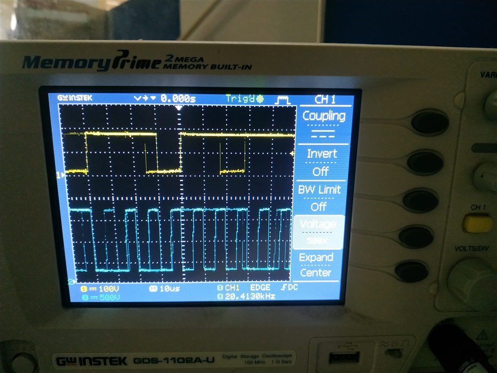
But I2C DETECT not working with nrf52840 DK. Please suggest how to debug this issue? We have an Oscilloscope!

Please comment out the for loop and set the address to 0x6F and then attach a captured trace of the SCL and SDA lines to this question.
Which pins are you using as TWI pins on the nRF52840 DK?
Please check scopes & info below:
NRF52840 DK I2C PINS Tried: (27,26) & (14,13), also tried 100kHz ~ 400kHz i2c frequency
#define SCL		           				 NRF_GPIO_PIN_MAP(0,14)
#define SDA		           				 NRF_GPIO_PIN_MAP(0,13)

/* TWI instance. */
static const nrf_drv_twi_t m_twi = NRF_DRV_TWI_INSTANCE(TWI_INSTANCE_ID);

    ret_code_t err_code;
    uint8_t address;
    uint8_t sample_data;
    bool detected_device = false;
		bool flag = false;

/**
 * @brief TWI initialization.
 */
void twi_init (void)
{
    ret_code_t err_code;

    const nrf_drv_twi_config_t twi_config = {
       .scl                = SCL,
       .sda                = SDA,
       .frequency          = NRF_DRV_TWI_FREQ_100K,
       .interrupt_priority = APP_IRQ_PRIORITY_HIGH,
       .clear_bus_init     = false
    };

    err_code = nrf_drv_twi_init(&m_twi, &twi_config, NULL, NULL);
    APP_ERROR_CHECK(err_code);

    nrf_drv_twi_enable(&m_twi);
}
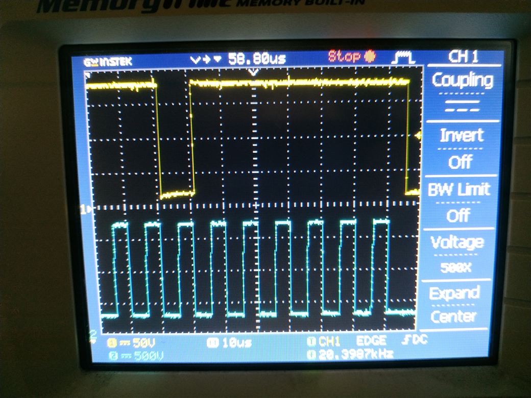
Yellow: SDA
Blue: SCL
HI Vishal,
I assume that the above trace is the address byte being transferred. If the MCP7940 has 0x6F as its TWI address, then you should expect to see 0b1101111, hten a READ bit followed by a ACK bit( SDA held low). From the first video, Scope of NRF52840 connected on I2C to MCP7940(Not Working), then I see 0b1101111 being sendt followed by a READ bit and then I think I see a ACK from the MCP7940, but I am not sure as I am only able to see if there are 8 or 9 CLK pulses before SDA is pulled high.Can you try to capture the entire TWI frame on the screen, i.e. 9 clk cycles on screen at the time? However, it would appear that the nRF52840 is just sending the 0x6F address and then issues a STOP condition as SDA goes high after SCL. It should wait for data from the MCP7940 by holding the CLK low, and then allow the MCP7940 to drive the clock line.
Best regards
Bjørn
//    for (address = 1; address <= TWI_ADDRESSES; address++)
//    {
				while(1)
				{
        err_code = nrf_drv_twi_rx(&m_twi, 0x6F, &sample_data, sizeof(sample_data));
        if (err_code == NRF_SUCCESS)
        {
            detected_device = true;
            NRF_LOG_INFO("TWI device detected at address 0x%x.\r\n", address);

        }
        NRF_LOG_FLUSH();
			}
please check if this works for you? Let me know if a logic analyzer is required?